Fork-type pallet-lifting device

a pallet-lifting device and fork-type technology, which is applied in the direction of lifting devices, hand carts with multiple axes, sledges, etc., can solve the problems of insufficient vertical movement of forks, insufficient fork-type positioning, and insufficient fork-type loading,

Inactive Publication Date: 2007-05-24
COOPER DAVID
View PDF16 Cites 37 Cited by
  • Summary
  • Abstract
  • Description
  • Claims
  • Application Information

AI Technical Summary

Benefits of technology

[0014] The hydraulic means, which is mounted to the frame means, includes supporting wheel means having opposing supporting wheels which, in cooperation with the steering wheel unit, is structured to selectively and vertically displace and suspend the first and second fork elements at a selected elevation above an underlying supporting surface; a horizontally oriented axle; a hydraulic motor structured to selectively rotate the horizontally oriented axle, and a linkage arrangement connecting the horizontally oriented axle to the opposing supporting wheels. The linkage arrangement includes a pair of first lever arms, each having a proximal end and a distal end; a pair of second lever arms, each having a proximal end and a distal end; a pair of third lever arms, each having a proximal end and a distal end; a pair of fourth lever arms, each having a proximal end and a distal end; and a pair of elongate links, each having a proximal end and a distal end, and each including a first link portion, a second link portion, and fastening means wherein the first and second link portions are slidable longitudinally relative to each other, and wherein the fastening means selectively fixes the respective overall length of the first link portion in combination with the second link portion, and wherein the proximal end of the first lever arm is longitudinally slidable along, but not radially pivotal about, the horizontally oriented axle; the distal end of the first lever arm is fixedly secured to the proximal end of the second lever arm, the distal end of the first lever arm and the proximal end of the second lever arm are pivotally connected to the frame means, the distal end of the third lever arm is fixedly secured to the proximal end of the fourth lever arm, the distal end of the third lever arm and the proximal end of the fourth lever arm are pivotally secured to a respective one of the first and second fork elements, each of the opposing supporting wheels is rotationally secured to the distal end of a respective one of the fourth lever arms, the relative lengths of the first and second lever arms and the angular relationship therebetween, and the relative lengths of the third and fourth lever arms and the angular relationship therebetween and relative to the lengths and angular relationship of the first and second lever arms are dimensioned such that the elevation of the fork front ends of the first and second fork elements above an underlying supporting surface is always substantially equal to the elevation of the fork rear ends of the first and second fork elements above the underlying supporting surface, and the proximal end of each of the elongate links is pivotally connected to the distal end of a respective one of the second lever arms and the distal end of each of the elongate links is pivotally connected to the proximal end of a respective one of the third lever arms.
[0015] The control means, which controls the hydraulic motor, includes a main handle pivotally mounted to the steering wheel-mounting mechanism about a horizontally oriented axis, the main handle being structured to activate the hydraulic motor, a biasing mechanism structured to bias the main handle to an upright position, and a release mechanism structured to cause the hydraulic motor to allow the horizontally oriented axle to freely rotate such that the first and second fork elements return to their lowermost positions.

Problems solved by technology

However, there are many instances when simple vertical movement of the forks is not sufficient.
For example, if the vehicle cannot be maneuvered into a certain orientation with respect to the load, the forks may not be properly oriented.
Still further, some loads, such as pallets, may not fit on forks that are oriented at a specific distance with respect to each other.
In some instances, a pallet may be loaded in an asymmetric manner, in which case, a fork lift that has symmetrically oriented forks may not be as efficient as possible.

Method used


Image

  • Fork-type pallet-lifting device
  • Fork-type pallet-lifting device
  • Fork-type pallet-lifting device

Examples


Embodiment Construction

[0025] Other objects, features and advantages of the invention will become apparent from a consideration of the following detailed description and the accompanying drawings.

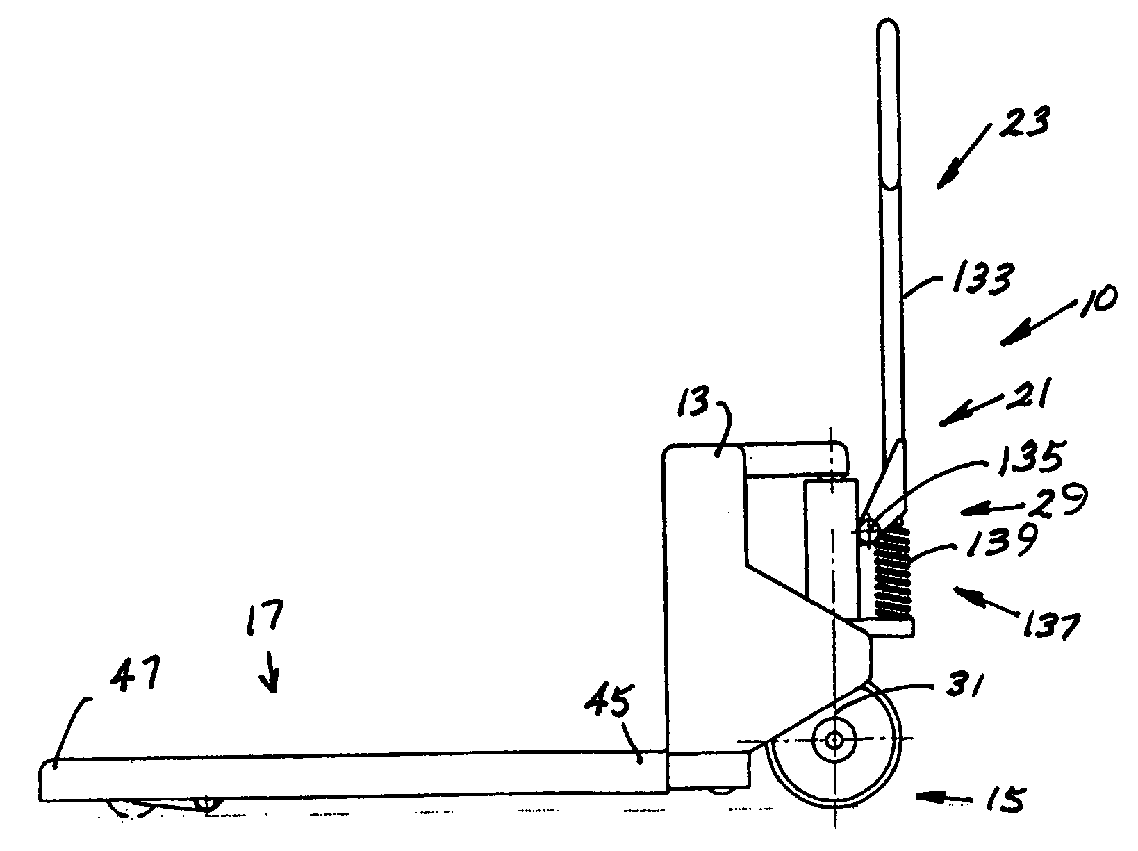
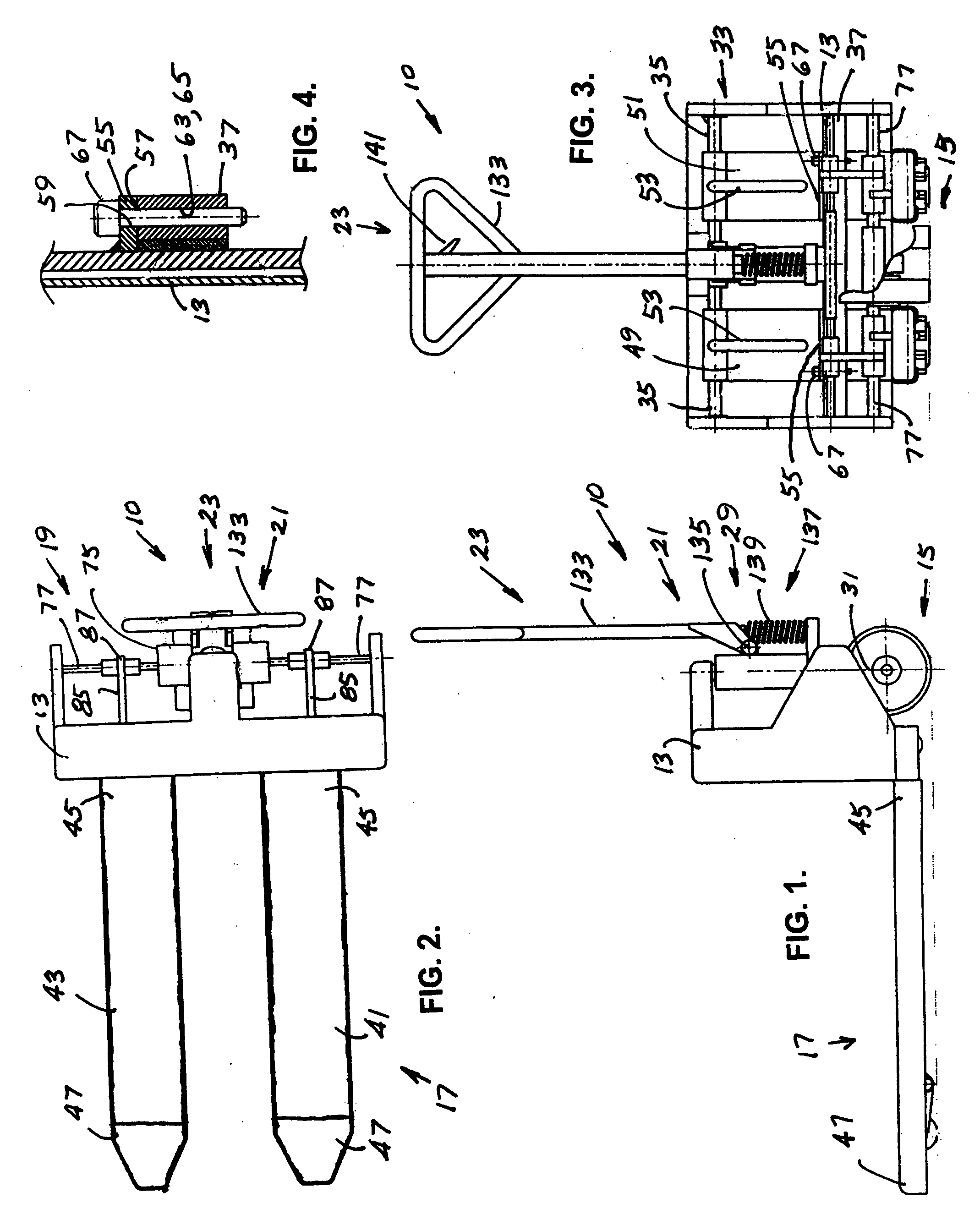
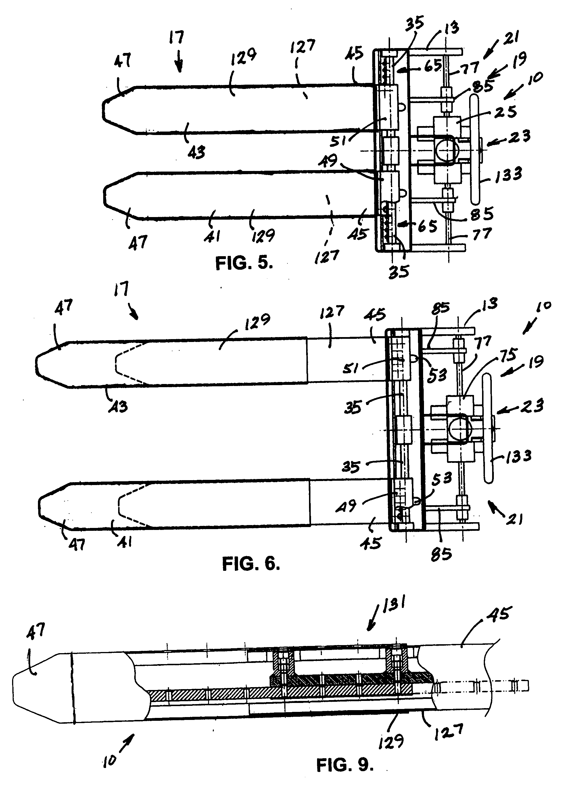
[0026] A fork-type pallet-lifting apparatus 10 as shown in FIGS. 1 through 9. The pallet-lifting apparatus 10 includes frame means 13, a steering wheel unit 15, a fork unit 17, fork-displacing means 19, hydraulic means 21, and control means 23.

[0027] The frame means 13 includes a steering wheel-mounting mechanism 29 having a vertically oriented axis 31 and a fork-supporting means 33, which includes a horizontally oriented support element 35 and a horizontally oriented crossbar 37. The steering wheel unit 15 is mounted to the steering wheel-mounting mechanism 29 to pivot about the vertically oriented axis 31.

[0028] The fork unit 17 is mounted on the fork-supporting means 33 and includes opposing first and second fork elements 41, 43, each having a fork front end 45 and a fork rear end 47. The fork-supporting me...


PUM


Abstract

A fork-type pallet-lifting device having frame means with a steering wheel-mounting mechanism and fork-supporting means a steering wheel unit mounted to the steering wheel-mounting mechanism, a fork unit with opposing first and second fork elements mounted to the fork-supporting means, fork-displacing means structured to selectively and separately allow lateral displacement of the first and second fork elements relative to each other, hydraulic means with supporting wheel means, a hydraulic motor, and a linkage arrangement structured to suspend the first and second fork elements at a selected elevation above an underlying supporting surface, and control means including a hydraulic motor, and a main handle and a release mechanism for controlling the hydraulic motor.

Description

BACKGROUND OF THE INVENTION [0001] 1. Field of the Invention [0002] The present invention relates to the general art of material and article handling, and to the particular field of hoists or loading equipment with means for additional movement. [0003] 2. Description of the Related Art [0004] Material and articles are often handled by a vehicle such as a fork lift truck. Such trucks generally have a mast to which forks are movably attached. These forks generally move up and down in a vertical direction to move material, pallets and the like from one level to another. [0005] However, there are many instances when simple vertical movement of the forks is not sufficient. For example, if the vehicle cannot be maneuvered into a certain orientation with respect to the load, the forks may not be properly oriented. Still further, some loads, such as pallets, may not fit on forks that are oriented at a specific distance with respect to each other. In some instances, a pallet may be loaded in...

Claims


Application Information

Patent Timeline
Patent Type & Authority Applications(United States)
IPC IPC(8): B66F9/18
CPCB62B3/06B62B2203/24B66F9/122B66F9/142
Inventor COOPER, DAVID
Owner COOPER DAVID
Why Eureka
Try Eureka