Polyaxial bone anchors with increased angulation

a polyaxial bone anchor and angulation technology, applied in the field of bone fixation devices, can solve the problems of inability to align the anchor head and the member, difficulty in spinal fixation and stabilization methods, and difficulty in spinal fixation and stabilization methods, and achieve the effect of greater flexibility

Active Publication Date: 2007-05-24
SYNTHES USA
View PDF99 Cites 527 Cited by
  • Summary
  • Abstract
  • Description
  • Claims
  • Application Information

AI Technical Summary

Benefits of technology

[0007] The anchor head, the internal sleeve, and primarily the locking element have features that allow the locking element to rotate or pivot within the anchor head. This in turn allows the pedicle screw to rotate or pivot around and away from the central axis of the anchor head at large angles. The pedicle screw or ho

Problems solved by technology

Surgeons may encounter difficulty with spinal fixation and stabilization methods because of difficulty aligning the spinal rod(s) with the U-shaped channels in the anchor heads of the screws or hooks.
For example, the anchor heads

Method used


Image

  • Polyaxial bone anchors with increased angulation
  • Polyaxial bone anchors with increased angulation
  • Polyaxial bone anchors with increased angulation

Examples


Embodiment Construction

[0023] The invention can be used to treat various spinal disorders including, for example, degenerative instabilities and instabilities due to decompression, tumors, infections, and fractures.

[0024] Note that while the polyaxial bone anchor is described and illustrated herein with reference to certain preferred or exemplary embodiments, the invention should not be limited to those preferred or exemplary embodiments. Furthermore, the features described and illustrated herein can be used singularly or in combination with other features and embodiments.

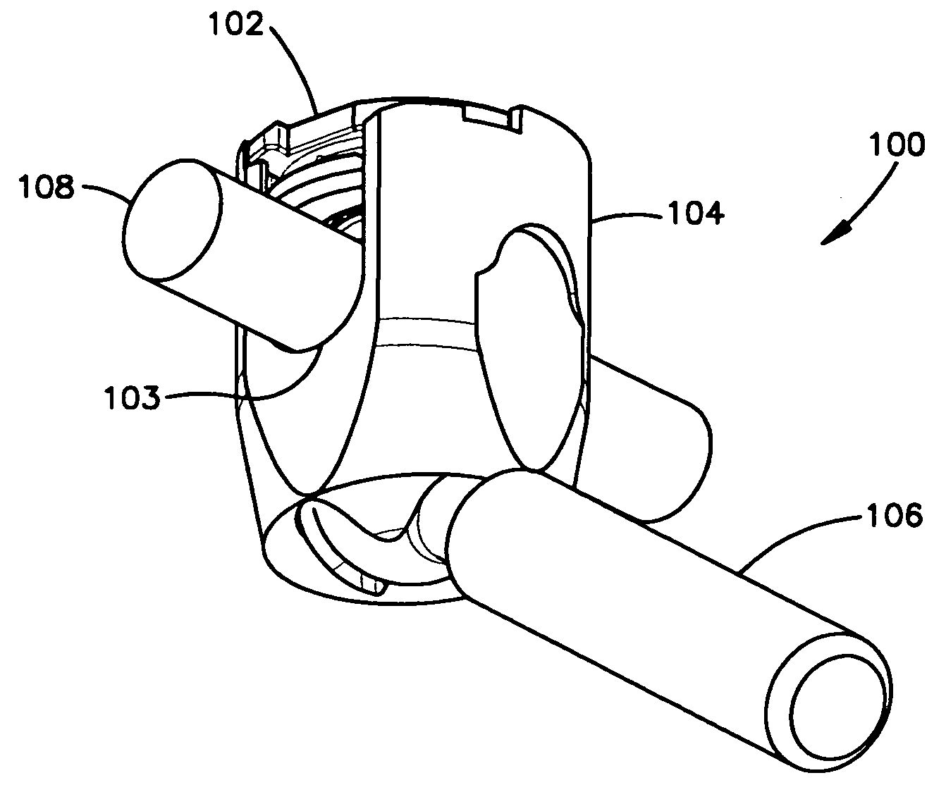
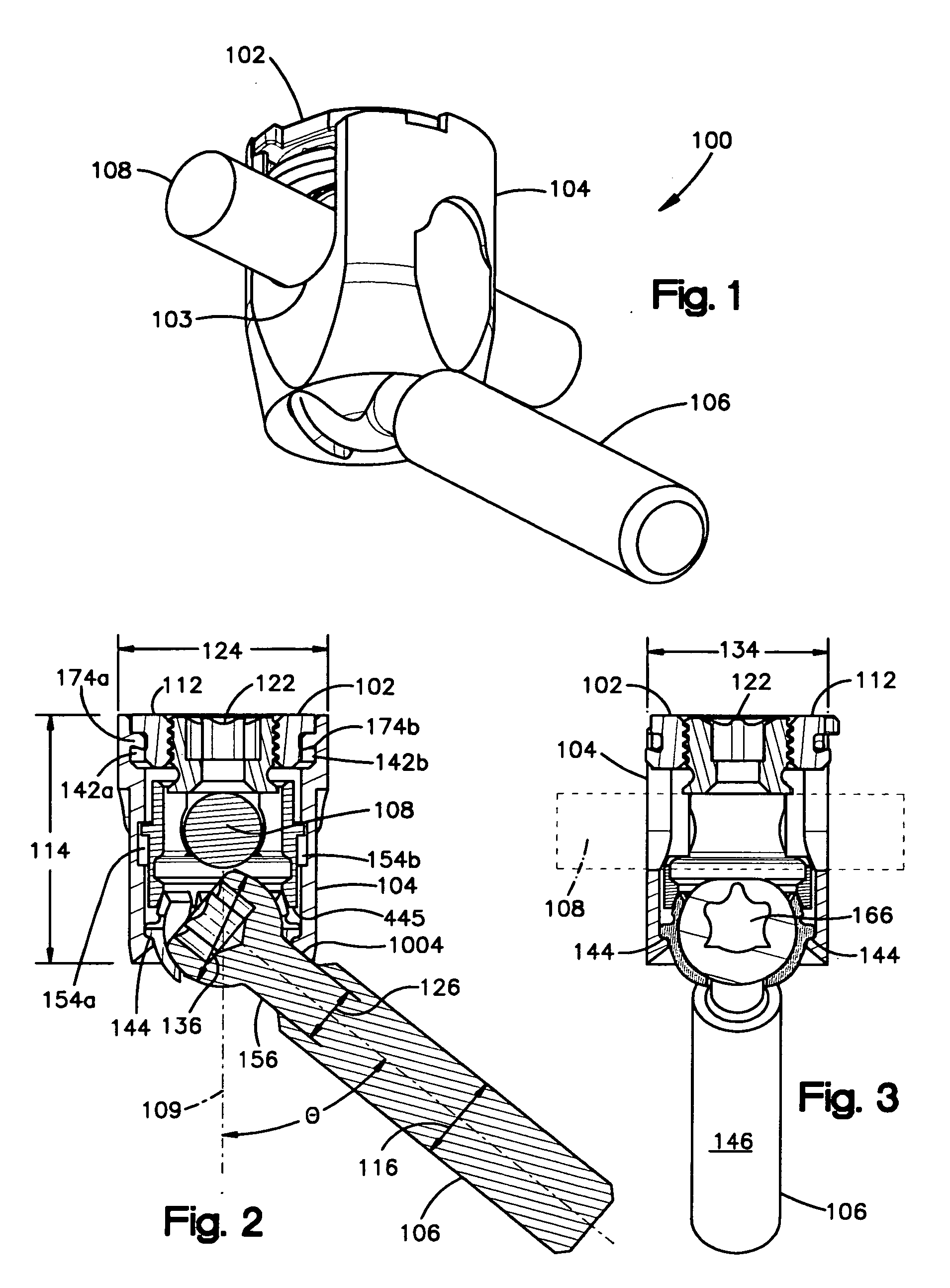
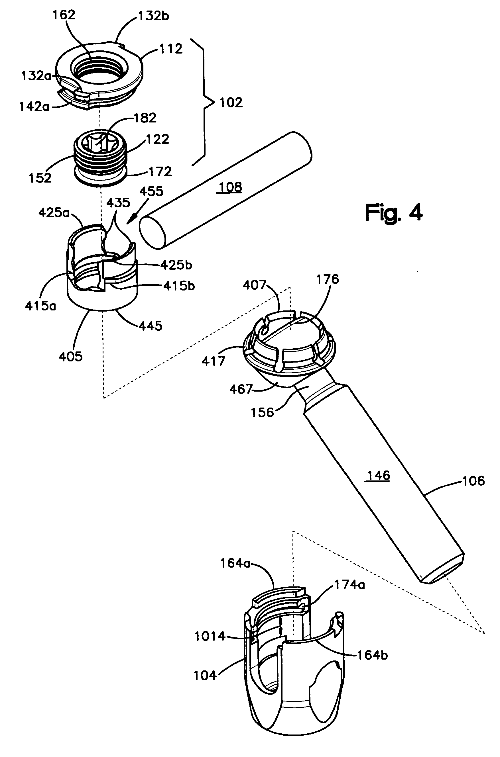
[0025]FIGS. 1-3 show a first embodiment of a polyaxial bone anchor. Polyaxial bone anchor 100 includes a fastener 102, an anchor head 104, and an anchor member 106. Fastener 102 is a locking cap that includes a locking ring 112 and a set screw 122 and may be similar or identical to that described in International Patent Application PCT / US2006 / 015692, internationally filed Apr. 25, 2006, which is incorporated herein by reference in its ...


PUM


Abstract

A polyaxial bone anchor has a locking element shaped and configured to allow an anchoring member (e.g., a screw or hook) to polyaxially rotate at large angles about a central axis of the bone anchor before compression locking the anchoring member within an anchor head.

Description

CROSS REFERENCE TO RELATED APPLICATION [0001] This claims the benefit of U.S. Provisional Application No. 60 / 739,100, filed Nov. 21, 2005.TECHNICAL FIELD OF THE INVENTION [0002] This invention relates to bone fixation devices and related methods of fixation. More particularly, this invention relates to polyaxial bone anchors, such as pedicle screws and hooks, having increased angulation for use in, for example, the posterior fixation of the spine. BACKGROUND OF THE INVENTION [0003] Polyaxial bone anchors and methods of use in treating spinal disorders are known. Typical methods involve anchoring at least two screws or hooks into the vertebrae, and fixing the screws or hooks along a spinal rod to position or immobilize the vertebrae with respect to one another. The screws or hooks commonly have anchor heads with U-shaped channels in which the spinal rod is inserted and subsequently clamped by a fastener, such as, for example, a threaded nut, set screw, or locking cap. These methods c...

Claims


Application Information

Patent Timeline
IPC IPC(8): A61F2/30
CPCA61B17/7032A61B17/7037A61B17/7038A61B17/7049
Inventor STRAUSBAUGH, WILLIAM L.SAIDHA, SEANWOLF, BOYD A.
Owner SYNTHES USA
Why Eureka
Try Eureka