Dust collecting apparatus of vacuum cleaner

a vacuum cleaner and dust collection technology, applied in the field of vacuum cleaners, can solve the problems of large loss of pressure, inability to evenly distribute dust discharged through the single inlet, and difficulty in preventing the loss of pressure of single inlet pressur

Inactive Publication Date: 2007-05-31
SAMSUNG GWANGJU ELECTRONICS CO LTD
View PDF0 Cites 40 Cited by
  • Summary
  • Abstract
  • Description
  • Claims
  • Application Information

AI Technical Summary

Benefits of technology

[0011] The present invention has been conceived to solve the above-mentioned problems occurring in the prior art, and an aspect of the present invention is to provide a dust collecting apparatus that can reduce a loss of pressure generated in a dust receptacle when drawn-in air flows into the dust receptacle.
[0012] Another aspect of the present invention is to provide a dust collecting apparatus that evenly distributes drawn-in air in a plurality of directions when air flows into a dust receptacle so that a separation efficiency of dust included in the drawn-in air can be enhanced.

Problems solved by technology

Then, air collides with the inner wall of the dust receptacle while flowing via the single inlet pipe into the dust receptacle so that a pressure is greatly lost.
The conventional cyclone dust collecting apparatus having a single inlet has difficulty in preventing the loss of pressure.
Additionally, dust discharged via the single inlet is not evenly distributed and flows continuously only from one direction.
Therefore, it is difficult to evenly distribute the dust along a circumferential direction of the dust receptacle and the whole separation efficiency of dust is decreased.

Method used


Image

  • Dust collecting apparatus of vacuum cleaner
  • Dust collecting apparatus of vacuum cleaner
  • Dust collecting apparatus of vacuum cleaner

Examples


Embodiment Construction

[0021] Exemplary embodiments of the present invention will be described in detail with reference to the annexed drawings. In the drawings, the same elements are denoted by the same reference numerals throughout the drawings. In the following description, detailed descriptions of known functions and configurations incorporated herein have been omitted for conciseness and clarity.

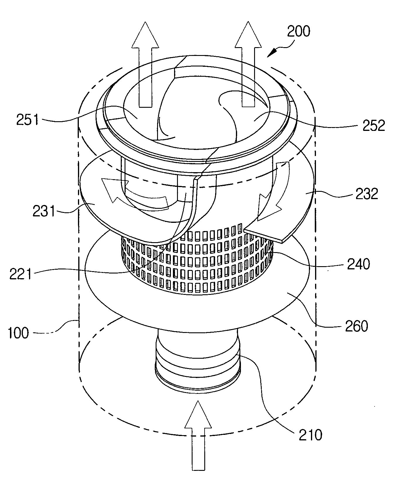
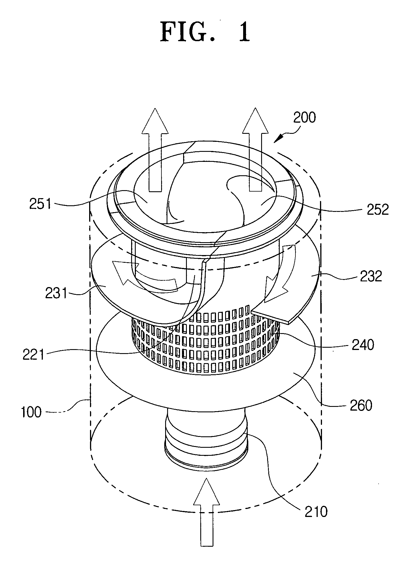
[0022] As shown in FIG. 1, a dust collecting apparatus according to an exemplary embodiment of the present invention comprises a dust receptacle 100 and a cyclone part 200 detachably inserted in the dust receptacle 100.

[0023] The dust receptacle 100 may be configured as a cylinder so that drawn-in air flowing from the cyclone part 200 can freely rotate in the dust receptacle 100.

[0024] The cyclone part 200 exerts a centrifugal force on drawn-in air by a vacuum source (not shown) to separate a dust from the drawn-in air in the dust receptacle 100.

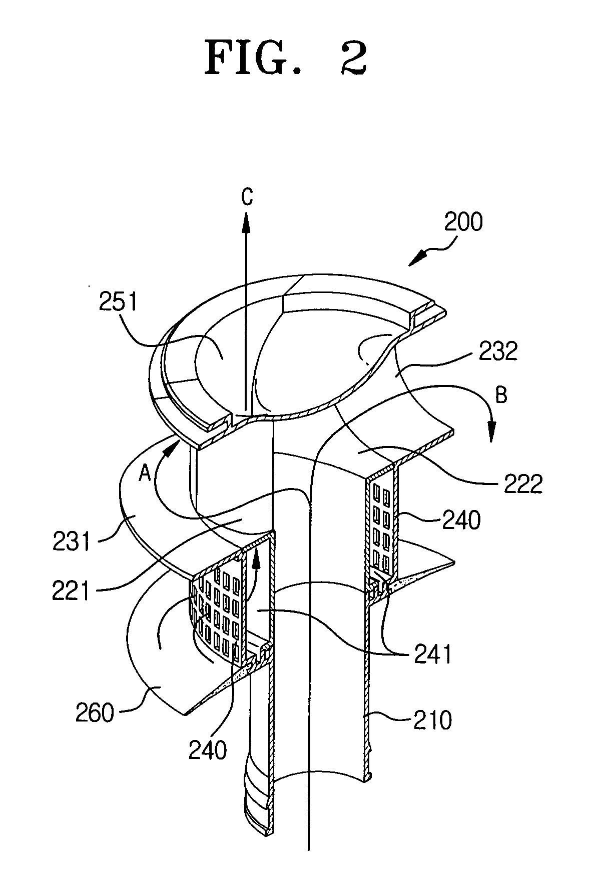
[0025] The cyclone part 200 has at a center a suction passag...


PUM

PropertyMeasurementUnit
centrifugal forceaaaaaaaaaa
outer circumferenceaaaaaaaaaa
outer diameteraaaaaaaaaa

Abstract

A dust collecting apparatus of a vacuum cleaner, the apparatus includes a dust receptacle to collect dust, and a cyclone part inserted in the dust receptacle. The cyclone part guides the drawn-in air vertically through a center of the cyclone part, allows the drawn-in air to flow in a tangential direction inside of the dust receptacle simultaneously from a plurality of directions into the dust receptacle and centrifugally separates the dust from the drawn-in air to discharge along the center.

Description

CROSS-REFERENCE TO RELATED APPLICATIONS [0001] This application claims benefit under 35 U.S.C. § 119 (a) of Korean Patent Application No. 2005-102614 filed on Oct. 28, 2005, the entire content of which are incorporated herein by reference. BACKGROUND OF THE INVENTION [0002] 1. Field of the Invention [0003] The present invention relates to a vacuum cleaner. More particularly, the present invention relates to a dust collecting apparatus that separates and collects dusts from drawn-in air. [0004] 2. Description of the Related Art [0005] Generally, a vacuum cleaner draws in dust-laden air from a cleaning surface and separates dust from the drawn-in air to clean the surface. The vacuum cleaner includes a dust collecting apparatus to separate dust from the drawn-in air and collect the dust. [0006] Recently, a cyclone dust collecting apparatus has been developed that separates dust from drawn-in air using a centrifugal force. The cyclone dust collecting apparatus has been popularized since...

Claims


Application Information

Patent Timeline
Patent Type & Authority Applications(United States)
IPC IPC(8): B01D50/00
CPCA47L9/1608A47L9/165A47L9/1658A47L9/16A47L9/10
Inventor JEON, KYOUNG-HUI
Owner SAMSUNG GWANGJU ELECTRONICS CO LTD
Why Eureka
Try Eureka