Systems and Methods for Generating Electricity Using a Thermoelectric Generator and Body of Water

Inactive Publication Date: 2007-05-31
AIR FORCE THE US SEC THE AIR FORCE +1
View PDF19 Cites 14 Cited by
  • Summary
  • Abstract
  • Description
  • Claims
  • Application Information

AI Technical Summary

Problems solved by technology

Operation and maintenance of these systems is expensive and utilizes significant natural resources and in some cases results in excessive pollution, either through hydrocarbon combustion or spent nuclear fuel rod disposal.
Oil may be considered a non-renewable source of power, which

Method used


Image

  • Systems and Methods for Generating Electricity Using a Thermoelectric Generator and Body of Water
  • Systems and Methods for Generating Electricity Using a Thermoelectric Generator and Body of Water
  • Systems and Methods for Generating Electricity Using a Thermoelectric Generator and Body of Water

Examples


Example

[0015] The present application now will be described more fully hereinafter with reference to the accompanying drawings, in which an exemplary embodiment of the application is shown. This application may, however, be embodied in many different forms and should not be construed as limited to the embodiments set forth herein; rather, this embodiment is provided so that this disclosure will be thorough and will fully convey the scope of the application to those skilled in the art. Like numbers refer to like elements throughout.

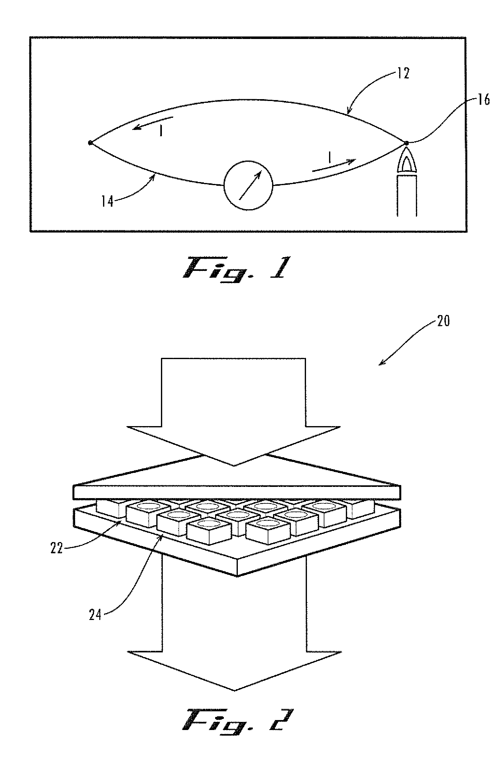
[0016] As illustrated in FIG. 1, continuously flowing electrical current may be created when a first wire 12 of a first material is joined with a second wire 14 of a second material and then heated at one of the junction ends 16. This is known as the Seebeck Effect. The Seebeck effect has two main applications: Temperature Measurement (thermocouple) and Power Generation. A thermoelectric system is one that operates on a circuit that incorporates both thermal and...


PUM


Abstract

A system for producing electrical power a thermoelectric generator including a thermopile, a hot junction, and a cold junction. A high temperature source may be thermally coupled to the hot junction wherein the high temperature source includes heat from within the earth's surface. A low temperature source may be thermally coupled to the cold junction wherein the low temperature source comprises cold water from a body of water. The thermopile generates electricity from a temperature gradient between the hot junction and the cold junction.

Description

RELATED APPLICATION DATA [0001] The present application also claims priority to U.S. Provisional Application No. 60 / 740,004 entitled “Systems and Methods for Generating Electricity Using a Thermoelectric Generator” filed on Nov. 28, 2005, which is incorporated herein by reference in its entirety.GOVERNMENT CONTRACT [0002] The U.S. Government has a license in this application pursuant to Contract Number F08630-03-C-0133 awarded by the U.S. Department of Defense.TECHNICAL FIELD [0003] This application relates generally to the field of electricity generation through the use of heat from within the earth's crust and more particularly to the use of thermoelectric generators in combination with heat from within the earth's crust and cool fluid for electricity generation. BACKGROUND OF THE APPLICATION [0004] Conventional systems for generating electricity for consumption and use by the public include nuclear power, fossil fuel powered steam generation plants and hydroelectric power. Operat...

Claims


Application Information

Patent Timeline
IPC IPC(8): H01L35/30H01L35/28
CPCH01L35/00H01L35/30H10N10/00H10N10/13
Inventor SUMRALL, THEODORE S.
Owner AIR FORCE THE US SEC THE AIR FORCE
Why Eureka
Try Eureka