

Band allocation control apparatus, band allocation control method, and band allocation control program
a band allocation and control apparatus technology, applied in the direction of time-division multiplex, data switching by path configuration, electrical devices, etc., can solve the problems of not considering the implementation of band control, the inability to use the entire band as above, and the significant degradation of execution throughpu
- Summary
- Abstract
- Description
- Claims
- Application Information
AI Technical Summary
Benefits of technology
Problems solved by technology
Method used
Image

Examples
Embodiment Construction
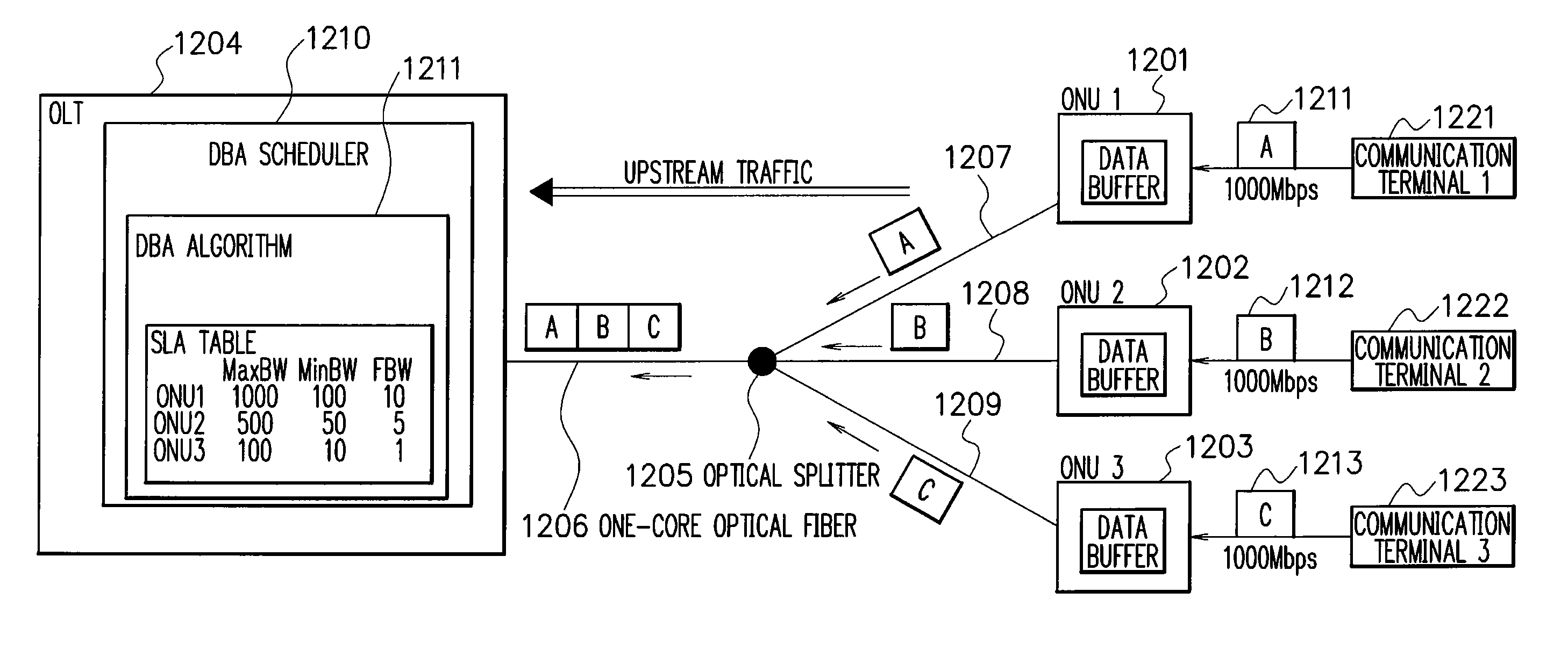
[0126] Referring now to FIG. 9, description will be given of aspects of a band allocation control apparatus in an embodiment.
[0127] In the embodiment, the band allocation control apparatus 1204 controls bands to be allocated to a plurality of ONUs 1201 to 1203. The apparatus 1204 sets the allocation bands according to the ratios of the maximum band limit values of the ONUs 1201 to 1203. This makes it possible to implement band control capable of guaranteeing impartiality between the service levels of the ONUs 1201 to 1203. Referring now to the accompanying drawings, description will be given of the embodiment of the band allocation control apparatus. In the following description, the apparatus 1204 will be referred to as an Optical Line Terminal (OLT).
[0128] Referring to FIG. 9, description will be given of a system configuration of the GE-PON system in the embodiment. FIG. 9 shows the system configuration of the GE-PON system.
[0129] In the embodiment of the GE-PON system, the OL...
PUM
 Abstract
Description
Claims
Application Information