Method and apparatus for increasing downstream bandwidth of a passive optical network using integrated WDM/power spitting devices and tunable lasers

downstream bandwidth technology, applied in the field of optical communication networks, can solve the problems that the practical and scalable solution of upgrading a power splitting pon to a wdm pon using the 2p1 devices cannot be found, and achieve the effect of increasing the downstream bandwidth of a passive optical network

Inactive Publication Date: 2007-05-31
LUCENT TECH INC
View PDF2 Cites 5 Cited by
  • Summary
  • Abstract
  • Description
  • Claims
  • Application Information

AI Technical Summary

Benefits of technology

[0006] Generally, methods and apparatus are disclosed for increasing downstream bandwidth of a passive optical network using integrated WDM / power spitting devices, such as the 2P1 devices, and one or more tunable lasers. According to one aspect of the invention, an optical multiplexing / demultiplexing system is disclosed that comprises an integrated wavelength division multiplexing / power spitting device having a WDM passive optical network and a power splitting PON; and one or more tunable lasers for selectively generating an optical signal of a desired wavelength for at least one subscriber, wherein the optical signal of a desired wavelength is communicated using the WDM PON.

Problems solved by technology

While these disclosed 2P1 devices effectively allow a WDM PON to send private signals to each subscriber, while the PS PON can be used simultaneously to broadcast signals, no practical solution has been proposed for upgrading a power splitting PON to a WDM PON using the 2P1 devices in a practical and scalable manner.

Method used


Image

  • Method and apparatus for increasing downstream bandwidth of a passive optical network using integrated WDM/power spitting devices and tunable lasers
  • Method and apparatus for increasing downstream bandwidth of a passive optical network using integrated WDM/power spitting devices and tunable lasers
  • Method and apparatus for increasing downstream bandwidth of a passive optical network using integrated WDM/power spitting devices and tunable lasers

Examples


Embodiment Construction

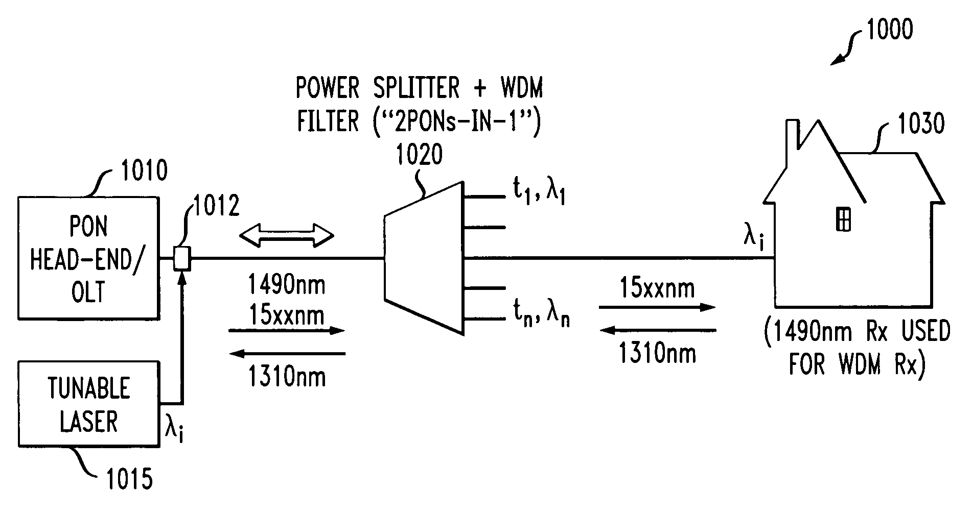
[0018] The present invention provides methods and apparatus for increasing downstream bandwidth of a passive optical network using integrated WDM / power spitting devices and tunable lasers. Among other benefits, the present invention provides wavelength-on-demand to individual subscribers. According to one aspect of the invention, tunable lasers allow one or more subscribers to be selectively addressed using an associated wavelength or range of wavelengths.

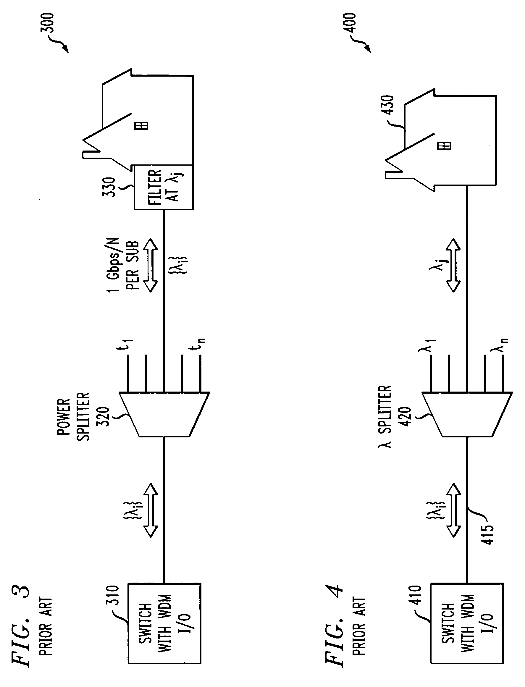
[0019]FIG. 3 is a schematic block diagram of a conventional power splitter optical multiplexing / demultiplexing system 300 employing DWDM channels. As shown in FIG. 3, the optical demultiplexing system 300 comprises a switch 310 having a wavelength division multiplexing input / output, such as a laser operating at a wavelength, λi. A power splitter 320 separates the optical signal, λi, into N different copies of the signal, λi, and a filter 330 associated with each subscriber filters the optical signal, λi, to isolate a passband, λj,...


PUM


Abstract

Methods and apparatus are disclosed for increasing downstream bandwidth of a passive optical network using integrated WDM/power spitting devices, such as the 2P1 devices, and one or more tunable lasers. An optical multiplexing/demultiplexing system is disclosed that comprises an integrated wavelength division multiplexing (WDM)/power spitting device having a WDM passive optical network (PON) and a power splitting PON; and one or more tunable lasers for selectively generating an optical signal of a desired wavelength for at least one subscriber, wherein the optical signal of a desired wavelength is communicated using the WDM PON. A method is also disclosed for communicating optical signals. One or more signals are broadcast to a plurality of subscribers using a power splitting passive optical network (PON). In addition, one or more private signals for at least one subscriber are generated using one or more tunable lasers; and are communicated to the at least one subscriber using a wavelength division multiplexing (WDM) PON.

Description

FIELD OF THE INVENTION [0001] The present invention relates generally to optical communication networks, and more particularly, to optical communication networks that include passive components for routing and distributing optical signals. BACKGROUND OF INVENTION [0002] Optical fiber networks are increasingly important for the distribution of voice, video, and data signals. Such systems generally involve a number of feeder fibers that emanate from a head-end office, and terminate at respective remote terminals. In a Fiber-To-The-Home or a Fiber-To-The-Curb system, optical signals are transmitted from each of these remote terminals to a number of optical network units over distribution fiber. Signals are transmitted optically or electrically to each optical network unit. [0003] Network architectures have been proposed for transmitting signals between the head-end office and the optical network units. FIG. 1 illustrates a conventional “2-PONs-In-1” (2P 1) device 100 that uses a passiv...

Claims


Application Information

Patent Timeline
Patent Type & Authority Applications(United States)
IPC IPC(8): H04J14/00
CPCH04J14/0226H04J14/0282H04J14/0246H04J14/0247H04J14/0252
Inventor MATTHEWS, MANYALIBO JOSEPH
Owner LUCENT TECH INC
Why Eureka
Try Eureka