

Image density control method and image forming apparatus
a control method and image technology, applied in the direction of electrographic process apparatus, instruments, optics, etc., can solve the problems of unwanted drop in the density of the solid image part and adherence of the carrier, excessive use of toner, and difficulty in maintaining a stable image density, etc., to achieve stable and high quality
Inactive Publication Date: 2007-05-31
RICOH KK
View PDF5 Cites 30 Cited by
- Summary
- Abstract
- Description
- Claims
- Application Information
AI Technical Summary
Benefits of technology
[0021] Thereupon, it is an object of the present invention to provide an image density control method in which, in a system that does not implement a paper process control (change the toner density control reference value between transfer sheets of paper by producing at least one reference patch on a transfer belt and detecting the density thereof on the transfer belt by means of a photosensor), high quality images can be stably mai
Problems solved by technology
In addition, low toner density results in an unwanted drop in the density of the solid image part and adherence of the carrier.
However, there is a desire for the excessive use of toner that occurs in actual practice when toner patterns are produced between sheets of paper to as far as possible be reduced, and correction based on production of reference toner patterns between sheets of paper is tending now towards an expanding of the interval between the production of the toner patterns, or indeed to not being performed at all.
How
Method used
View moreImage
Smart ImageViewing Examples

Examples
 PUM
 Abstract
An image density control method for an image forming apparatus in which, in order to keep the development capability constant over time, the toner density in the developer is manipulated to an appropriate range by changing the toner density control reference value in accordance with the toner replacement amount in a fixed time period by ascertaining changes in the image coverage of the output images, and by changing the image forming conditions at predetermined execution intervals.
Description
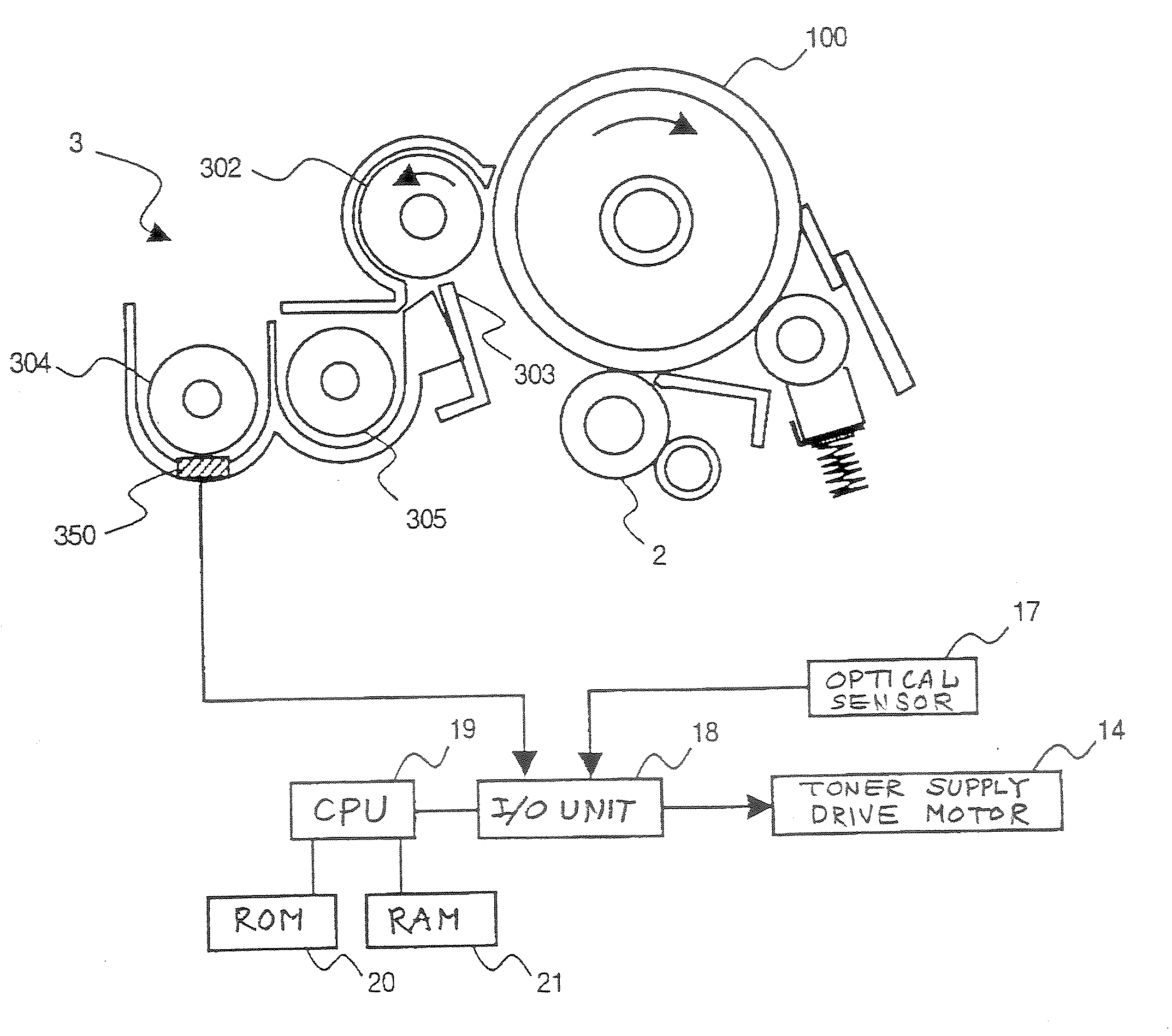
BACKGROUND OF THE INVENTION [0001] 1. Field of the Invention [0002] The present invention relates to an image density control method for an electrophotographic type image forming apparatus such as a copier, printer or facsimile device. [0003] 2. Description of the Related Art [0004] The demand for improved copier and laser printer image quality in recent years has been simultaneously accompanied by a desire for improved image durability and stability. In other words, there is a need for images that are minimally affected by change in the usage environment (including continuous printing and intermittent printing) and that remain stable over time to be provided. Two-component developer systems in which a two-component developer comprising a non-magnetic toner and magnetic carrier (hereinafter referred to as a developer) that is held on a developer carrier (hereinafter referred to as a development sleeve), and in which development is based on a magnetic brush being formed by housed mag...
Claims
Login to View More Application Information
Patent Timeline
 IPC IPC(8): G03G15/08
CPCG03G2215/0119G03G15/0853G03G2215/0822
InventorTANAKA, KAYOKOFUJIMORI, KOHTAHIRAYAMA, YUJITAKEUCHI, NOBUTAKAHASEGAWA, SHINKATO, SHINJIENAMI, TAKASHIKOBAYASHI, KAZUMISHIMIZU, KIICHIROU
OwnerRICOH KK