
Assembly for mounting paint spray gun to extension pole with paint applicator

a technology for spraying guns and extension poles, which is applied in the direction of carpet cleaners, applications, cleaning machines, etc., can solve the problems of high cost of units, difficult installation, and particularly problematic configuration

Inactive Publication Date: 2007-05-31
COATINGS MANAGEMENT SYST
View PDF4 Cites 25 Cited by
  • Summary
  • Abstract
  • Description
  • Claims
  • Application Information

AI Technical Summary

Benefits of technology

[0009] In particularly, according to one aspect of the present invention, a paint application assembly comprises an elongated pole presenting opposite proximal and distal ends. The assembly further includes a paint applicator secured to said pole adjacent the distal end thereof, as well as a sprayer mounting assembly detachably securing a trigger-controlled sprayer to the pole adjacent the distal end thereof in order to emit paint in proximity to the applicator. The mounting assembly includes a shiftable element selectively engageable with the trigger to control actuation thereof. The mounting assembly further includes a manually operable actuator adjacent the proximal end of the pole, with the actuator and element being operably interconnected so that the actuator is operable to contr

Problems solved by technology

Those ordinarily skilled in the art will appreciate that such a configuration is particularly problematic when changing paint colors or types.
Furthermore, as with all reusable painting equipment, the device must be thoroughly cleaned after use; however, the unique construction and paint passageways cause such cleaning thereof to be time consuming and tedious.
Here again, these units are relatively expensive and present problems similar to those noted above.
However, this type of pole mechanism is of complicated design and has several shortcomings.
For example, the device depicted in the '922 patent is not suitable for use with a standard trigger-operated paint sprayer.
Nor does the device show or suggest the use of a paint applicator on the pole.
Finally, the device is not suitable for use in retrofit applications, where an existing extension pole is converted for use with the proximally controlled but distally mounted accessory.

Method used


Image

  • Assembly for mounting paint spray gun to extension pole with paint applicator
  • Assembly for mounting paint spray gun to extension pole with paint applicator
  • Assembly for mounting paint spray gun to extension pole with paint applicator

Examples


Embodiment Construction

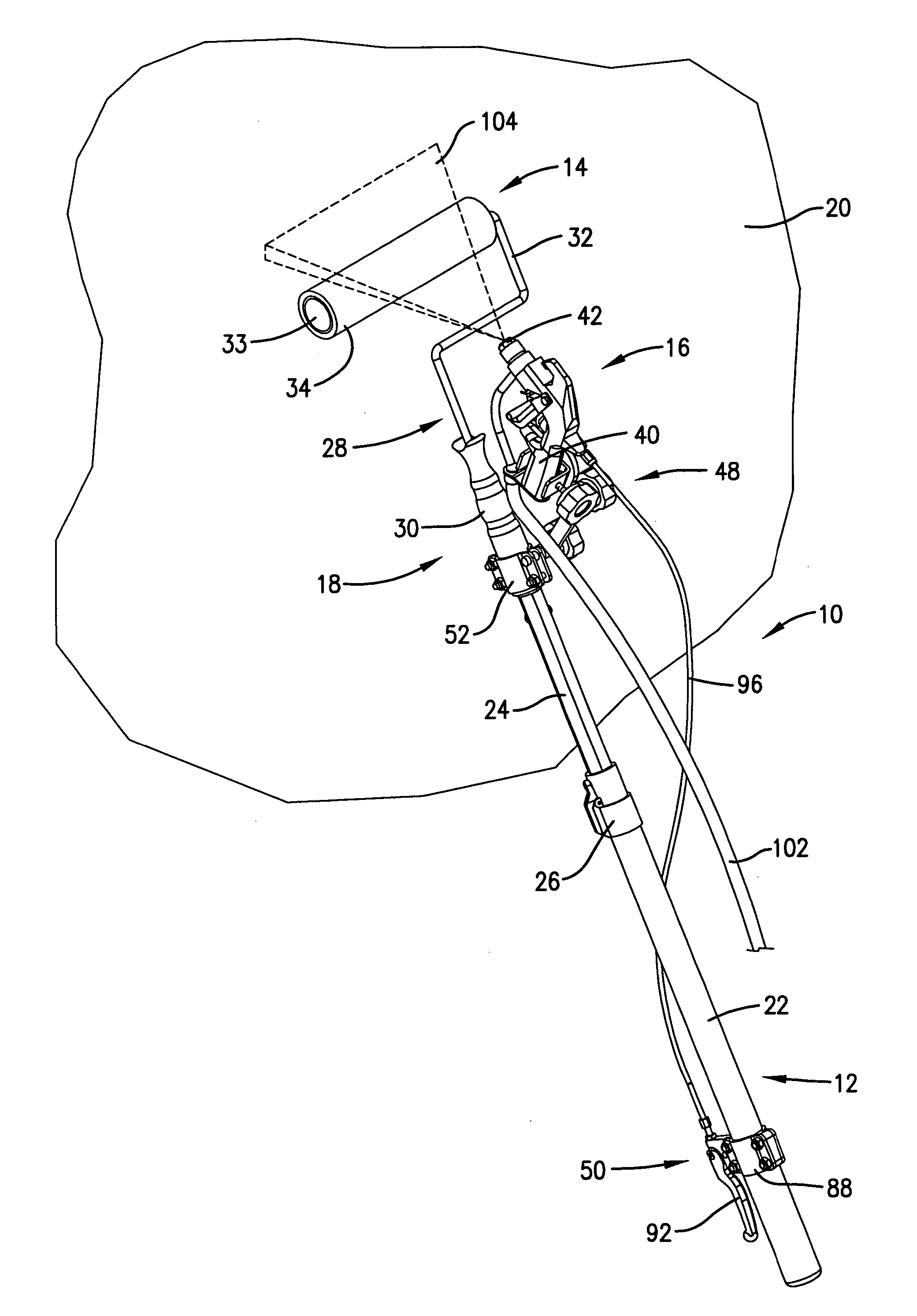
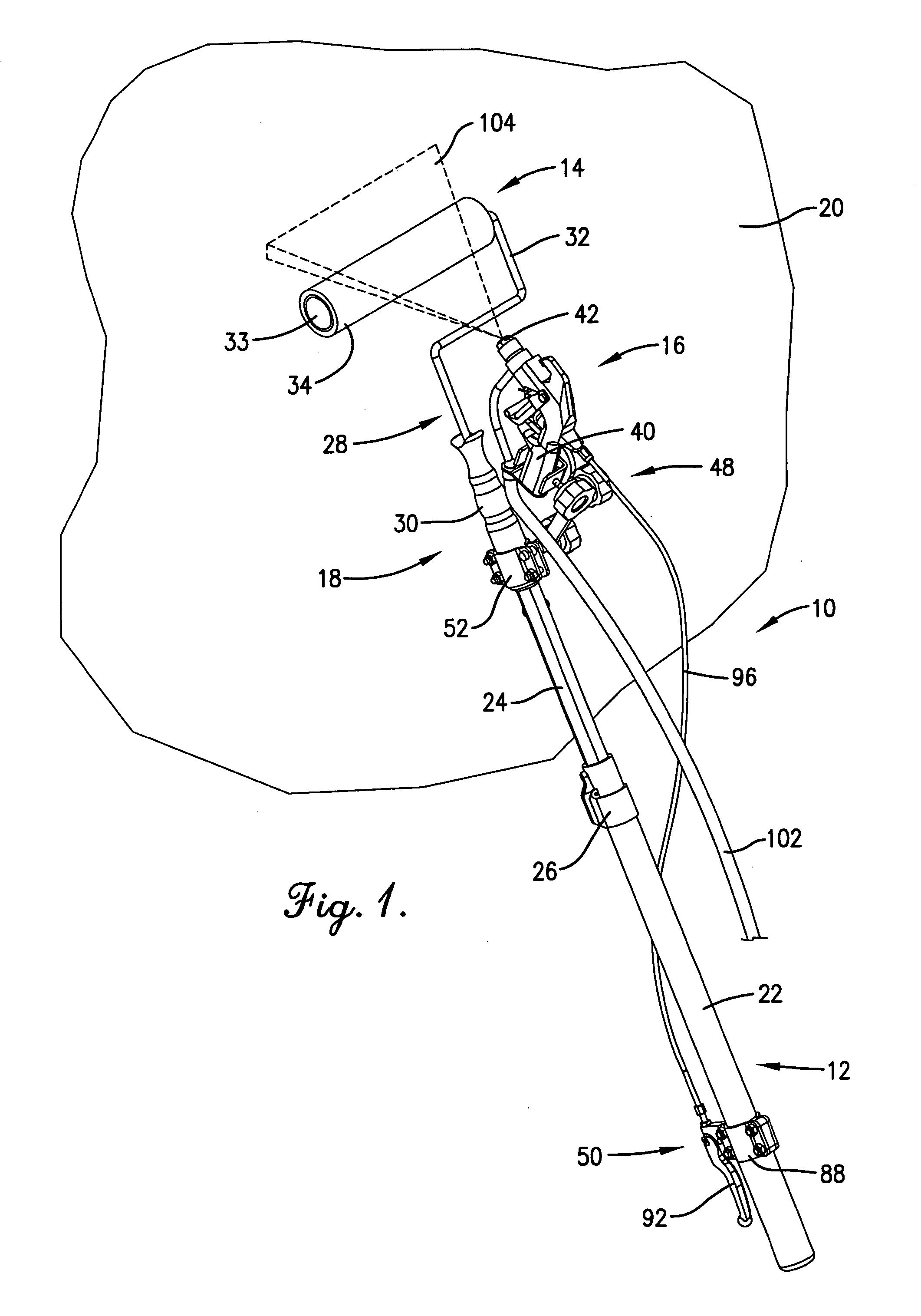
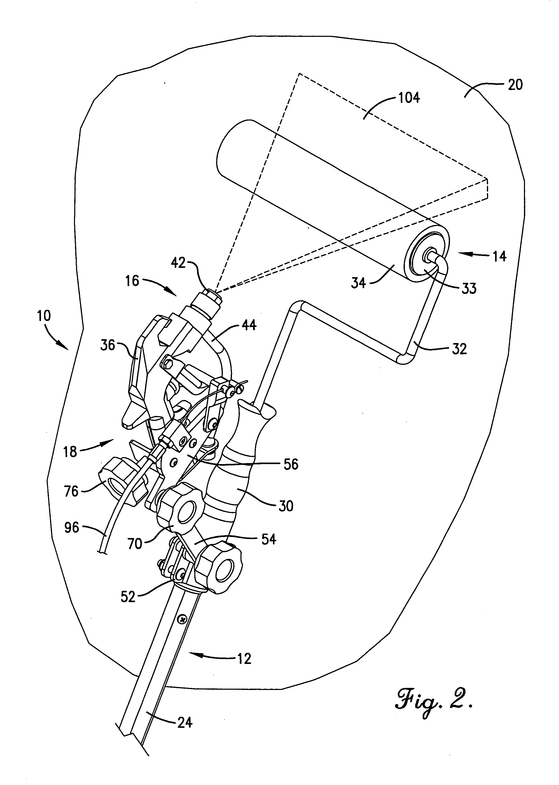
[0022] Turning now to the drawings, a paint application assembly 10 is illustrated in FIGS. 1-5 and broadly includes an elongated telescopic pole 12, an end-mounted paint applicator 14, paint sprayer 16, and a mounting assembly 18 for detachably securing the sprayer 16 and associated control structure onto pole 12. The application assembly 10 is designed for rapid and easy application of paint onto a wall surface 20 or the like. A particular feature of the invention is that it permits a standard pole-type painting device to be retrofitted with a conventional sprayer.

[0023] In more detail, the pole 12 is itself conventional and includes a pair of telescopically interfitted sections 22 and 24. The section 22 provides a hand grip, whereas the section 24 is designed to support a paint applicator 14 (or other accessory). The pole 12 has a locking mechanism 26 adjacent the upper end of section 22 for locking the section 24 in place at a selected extension length. In this fashion, the pol...


PUM


Abstract

A paint applicator (10) for application of paint to a surface (20) is provided which includes a telescopic pole (12) supporting a paint applicator (14) (e.g., a paint roller (28)) and a paint sprayer (16). The sprayer (16) is detachably secured to pole (12) by means of adjustable mounting assembly (48) and is operatively connected with an operating lever (92) also supported on pole (12) through assembly (50). The assemblies (48, 50) and sprayer (16) may be retrofitted onto otherwise conventional pole-type paint applicators. The applicator (10) may be operated by a single user to selectively spray paint onto the surface (20) as needed while appropriately spreading the paint using applicator (14).

Description

BACKGROUND OF THE INVENTION [0001] 1. Field of the Invention [0002] The present invention is broadly concerned with paint application equipment, such as pole-type paint application assemblies having both a spreading device (e.g., a roller or pad) together with a pole-mounted selectively operable paint sprayer. More particularly, the invention is concerned with such application assemblies wherein a trigger-operated spray gun is mounted to the extension pole adjacent the paint applicator. The present invention is particularly useful as a retrofit onto a conventional pole-type paint applicator, although the principles of the invention are not so limited. [0003] 2. Description of the Prior Art [0004] It has long been recognized that extending a user's reach through an extension pole is advantageous in painting wall or ceiling surfaces. A paint roller mounted on a pole allows the user to work beyond his or her natural reach and thus makes a painting job easier and more efficient. [0005] ...

Claims


Application Information

Patent Timeline
IPC IPC(8): A47L13/00B43M11/02
CPCB05B15/064B05C17/0205B05B15/628
Inventor DAVIS, KURTIS J.
Owner COATINGS MANAGEMENT SYST
Learn More