System and method for mounting a plate to an adhesive member

a technology of adhesive members and mounting plates, applied in the printing industry, can solve the problems of high sleeve cost per unit, uneven alignment of finished products, and high cost of sleeves, and achieve the effect of removing misalignment or skew caused by improperly aligned printing plates

Inactive Publication Date: 2007-06-07
GERALD & TERESA ANN GARTNER OR THEIR SUCCESSORS
View PDF10 Cites 12 Cited by
  • Summary
  • Abstract
  • Description
  • Claims
  • Application Information

AI Technical Summary

Benefits of technology

This patent describes how to make sure that printing plates are always aligned correctly when they are attached to an adhesive sheet for use in a printing press. By aligning the markings on the ends of the printing plate with those on the adhesive sheet, and then sticking them together, it becomes easy to ensure that all the printed material comes out perfectly straight. This technique helps avoid any mistakes or errors caused by poor alignment between the printing plates.

Problems solved by technology

The technical problem addressed in this patent text relates to developing a more precise and affordable system for aligning printing plates when producing printed products. Current methods involve attaching plates to a cylinder using sticky back and then placing them into position during printing. However, this often results in poor alignment and wastes resources. There is a need for a new approach that allows for better precision and efficiency in the placement of printing plates.

Method used


Image

  • System and method for mounting a plate to an adhesive member
  • System and method for mounting a plate to an adhesive member
  • System and method for mounting a plate to an adhesive member

Examples


Embodiment Construction

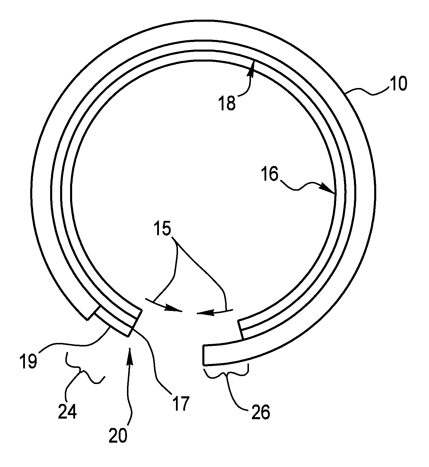
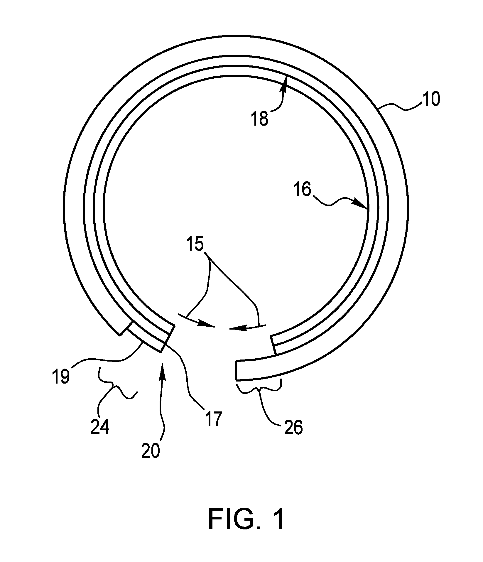
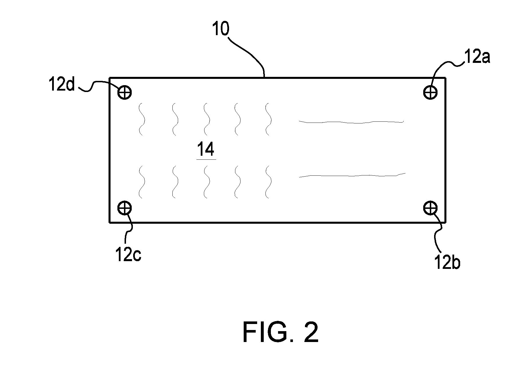
[0022] The present invention features a novel system and method for forming a photographically or digitally generated printing plate or other generally flat, planar object into a circular sleeve that can then be inserted onto the drum of a printing press or other device. The invention assumes that the printing plate 10, FIG. 2, will have imaged or otherwise placed thereon one or more and preferably four (4) alignment marks 12 in addition to the indicia 14 (text and / or images) to be printed. Although the present invention will be explained in connection with the flexography method of printing, this is not a limitation of the present invention.

[0023] Flexography is a “relief” printing process meaning that the image portion of the plate is raised above the “floor” of the plate (such as a rubber stamp). The “letterpress” method is also a relief printing process whereas offset lithography plates are essentially planar and rely on the chemistry of the printing area. The present invention...


PUM

PropertyMeasurementUnit
Adhesivityaaaaaaaaaa

Abstract

A system and method for adhering and aligning a generally flat, planar object to an adhesive layer, and for facilitating the mounting of the generally flat planar object, such as a printing plate, in near perfect alignment in a cylindrical manner. The method includes providing a generally flat, planar object such as a printing plate and an adhesive member having an adhesive layer at least on one surface. The adhesive member is preferably approximately the same size as the printing plate. The printing plate is mounted to the adhesive member such that there is one edge of the adhesive member which is not initially covered by the printing plate and one edge of the printing plate which overhangs the adhesive member. The combined adhesive member/printing plate structure is next rolled into a cylindrical form and held in place on a device which allows alignment marks on the printing plate to align the two ends of the printing plate prior to the printing plate being fully adhered to the adhesive member. The resulting sleeve structure can then be inserted onto a plate cylinder and this assembly utilized in a printing press. In another embodiment, the adhesive member is provided as a single or multi-layered structure pre-rolled into a generally circular form.

Description


Claims


Application Information

Patent Timeline
Owner GERALD & TERESA ANN GARTNER OR THEIR SUCCESSORS
Why Eureka
Try Eureka