

Ladder, in particular swimming-pool ladder
- Summary
- Abstract
- Description
- Claims
- Application Information
AI Technical Summary
Benefits of technology
Problems solved by technology
Method used
Image

Examples
Embodiment Construction
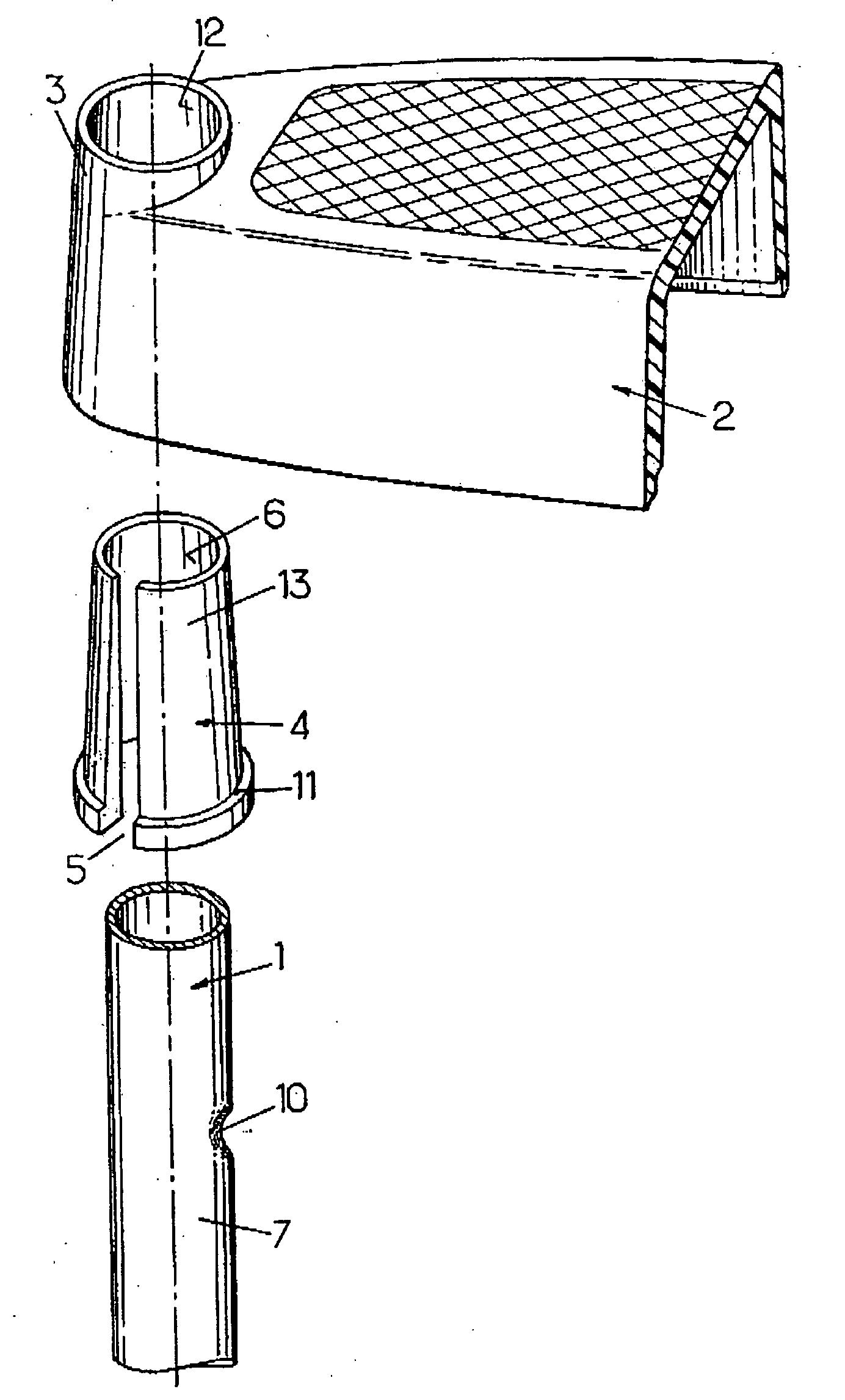
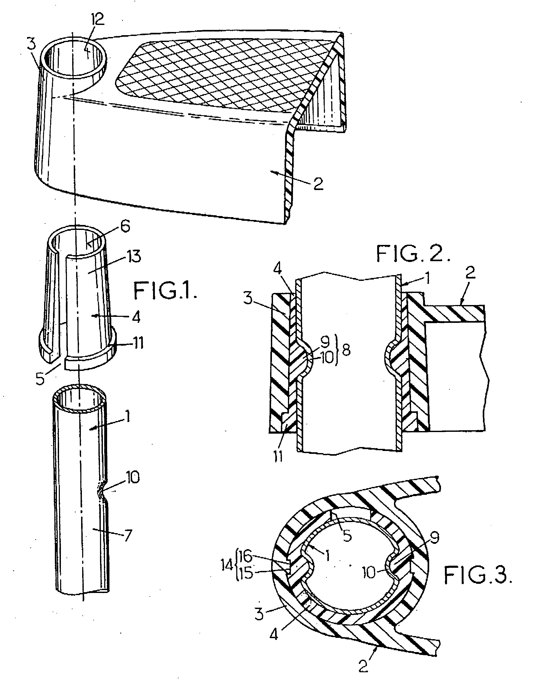
[0021] The invention relates, as stated above, to a ladder comprising two uprights and at least one rung fastened to said uprights, in general a plurality of superposed rungs fastened to the uprights. FIGS. 1 to 3, to which reference will first be made, show: [0022] a portion of one of the uprights 1, in tubular form, in particular metallic; in the example illustrated, this is a tubular upright in the form of a cylinder of revolution, this seeming to be the most frequent case in practice; [0023] an end part of a rung 2 which may be of any shape and which comprises, at its end, a tubular sleeve 3 coaxially surrounding the upright 1; in the example illustrated, the rung 2 is assumed to be produced as a whole to virtually from injection-moulded plastic; and [0024] a tubular locking insert ring 4 engaged between the upright 1 and the tubular sleeve 3 of the rung 2 in order to lock the rung 2 axially on the upright 1; the ring 4 may itself advantageously consist of injection-moulded plas...
PUM
 Abstract
Description
Claims
Application Information