Passive radio frequency identification (RFID) transponder/reader system and method for survey marker location

a radio frequency identification and transponder technology, applied in direction finders using radio waves, instruments, reradiation, etc., can solve the problems of inability to locate survey markers, time-consuming and difficult to locate existing survey markers, etc., to achieve efficient and cost-effective identification and

Inactive Publication Date: 2007-06-07
ADAMS DAVID RODNEY +1
View PDF5 Cites 25 Cited by
  • Summary
  • Abstract
  • Description
  • Claims
  • Application Information

AI Technical Summary

Benefits of technology

[0014] 4.1—The present invention provides a system, whereby property boundary survey markers may be more efficiently and cost effectively identified and located (compared to prior art) after an original property survey.
[0015] 4.2—The present invention has potential to become an integral part of required standard survey and mapping infrastructure regulation in the United States and eventually worldwide.
[0016]FIG. 1—Block diagram view of system
[0017]FIG. 2—Block diagram view of controller
[0033]FIG. 1 is a diagrammatic view of a transponder / reader system for the detection of survey markers constructed according to the present invention.

Problems solved by technology

Property boundary lines often run through poorly accessible remote areas.
While survey markers on small urban lots are relatively easy to locate, larger pieces of property usually present a challenging and time consuming effort to locate existing survey markers, especially if they are buried or obscured by overgrowth of vegetation.
In actual experience, some survey markers cannot be located, even with professional equipment.

Method used


Image

  • Passive radio frequency identification (RFID) transponder/reader system and method for survey marker location
  • Passive radio frequency identification (RFID) transponder/reader system and method for survey marker location
  • Passive radio frequency identification (RFID) transponder/reader system and method for survey marker location

Examples


Embodiment Construction

[0035] 8.1—In the following description, like reference characters designate like or corresponding parts throughout the several views. Also in the following description, it is to be understood that such terms as “forward,”“front,”“back,”“right,”“left,” and the like are words of convenience and are not to be construed as limiting terms.

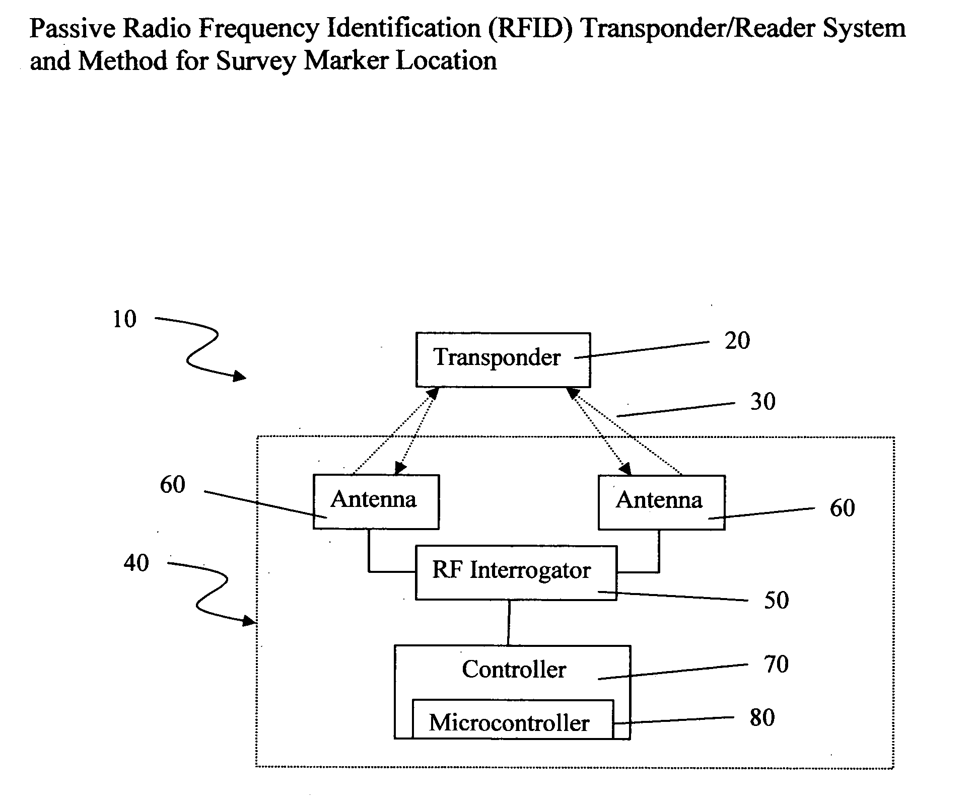
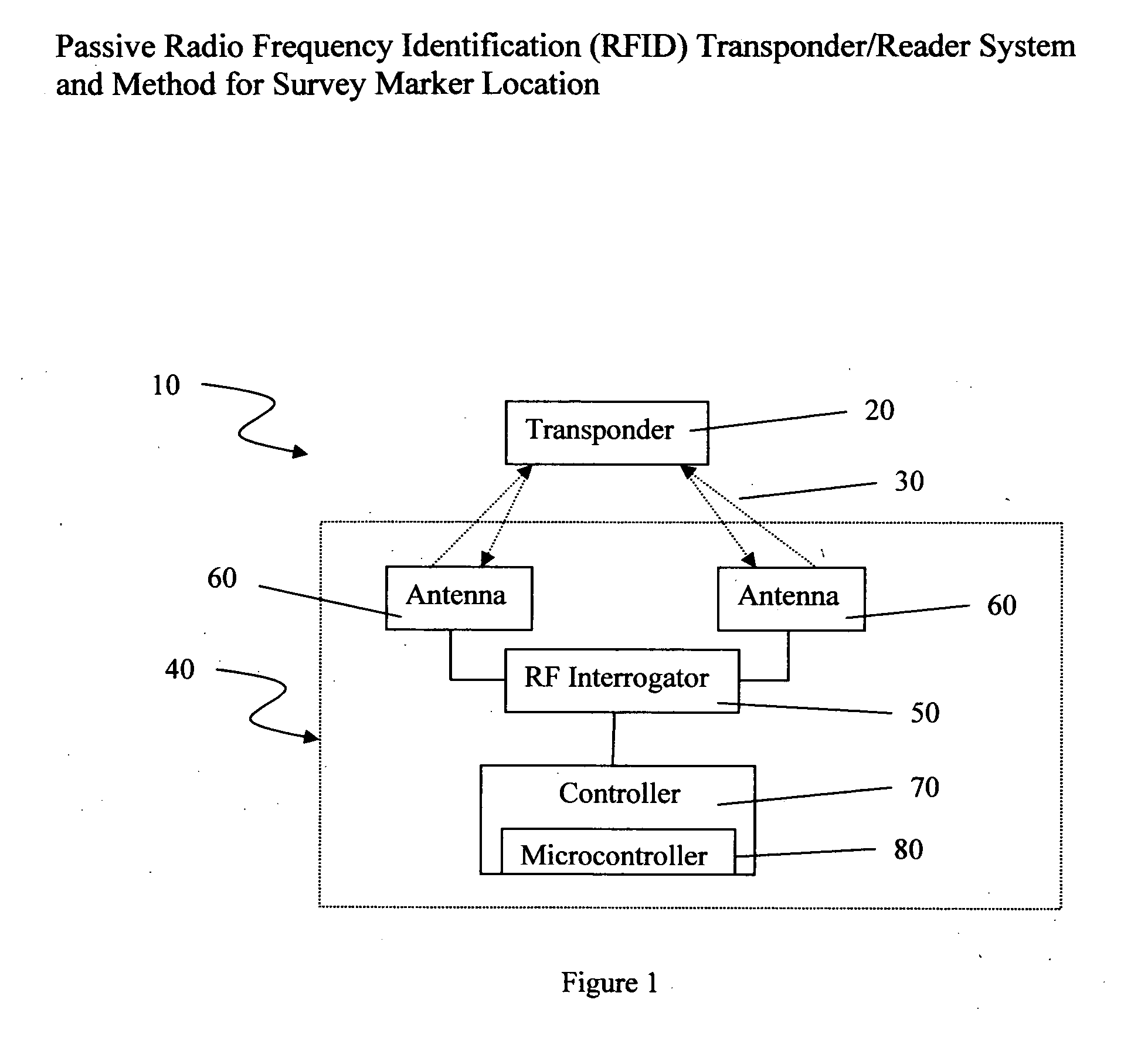
[0036] 8.2—Referring to the drawings in general, the illustrations are for the purpose of describing a preferred embodiment of the invention and are not intended to limit the invention thereto. As best seen in FIG. 1, the detector system, generally described as 10, includes a transponder 20, in discontinuous radio frequency communication 30 with a portable RF transponder detection system, generally described as 40. The portable RF transponder detection system is composed of an RF interrogator 50 connected to at least one antenna 60 and the controller 70, which contains the microcontroller 80.

[0037] 8.3—More particularly, the transponder 20 is prefera...


PUM


Abstract

A system designed to identify survey markers that are obscured by an accumulation of dust and dirt or overgrowth of vegetation. The system provides for automatic detection of survey markers using passive radio frequency transponder technology to detect the immediate presence of a tagged survey marker and read additional unique identification data corresponding to said marker. The operator can be signaled audibly and/or visually when a tagged survey marker is detected. The transmitter and antennae are mounted in a handheld or portable unit. An integrated microprocessor performs the requisite algorithms needed to process the reply from one or more RFID (Radio Frequency Identification) tags and generate the alert signals for the operator alerts. Once the RFID tagged survey marker has been located, it can be cleared of accumulated dust, dirt and overgrowth of vegetation to make it visible for confirming the property boundary. Handheld RFID programmers are used to load or record important identification data in the attached tag, regarding latitude-longitude location, and other pertinent survey data.

Description

1. BACKGROUND OF THE INVENTION [0001] 1.1—Field of the Invention [0002] The present invention relates generally to systems for the detection and location of hidden survey markers and, more particularly, to a RFID transponder / reader system for the detection and location of transponder-tagged survey markers during re-surveying operations and for the storage and transmission of information related to the transponder-tagged survey marker. [0003] 1.2—Description of the Prior Art [0004] Property boundary lines often run through poorly accessible remote areas. These boundary lines generally must be re-discovered by survey prior to building fences or other improvements to the property, or transferring ownership of the property. While survey markers on small urban lots are relatively easy to locate, larger pieces of property usually present a challenging and time consuming effort to locate existing survey markers, especially if they are buried or obscured by overgrowth of vegetation. The be...

Claims


Application Information

Patent Timeline
Patent Type & Authority Applications(United States)
IPC IPC(8): G08B13/14G08B1/08G08B5/22G01S1/00G01S3/02
CPCG01C15/00G01C15/04G01S13/751
Inventor ADAMS, DAVID RODNEYFEDUKOWSKI, DONNA LYNN
Owner ADAMS DAVID RODNEY
Why Eureka
Try Eureka