
LED lights with matched AC voltage using rectified circuitry

a technology of rectified circuitry and led lights, applied in the field of decorative light strings, can solve the problems of poor cost effectiveness, long life of leds, and low cost of current sources

Inactive Publication Date: 2007-06-07
FIBER OPTIC DESIGNS
View PDF4 Cites 54 Cited by
  • Summary
  • Abstract
  • Description
  • Claims
  • Application Information

AI Technical Summary

Benefits of technology

[0013] It is another object of this invention to provide a method and preferred embodiment that matches the half-wave rectified forward voltage rating of the LED's coupled in series to the half-wave, rectified AC power input without the need for additional power conversion.
[0014] It is another object of this invention to provide a method and preferred embodiment that matches the filtered, half wave rectified forward voltage rating of the LED's coupled in series to the filtered, half-wave rectified AC power input without the need for additional power conversion.

Problems solved by technology

First, as a device, LEDs have a very long lifespan, compared with common incandescent and fluorescent sources, with typical LED lifespan at least 100,000 hours.
Fourth, with newer doping techniques, LEDs are becoming increasingly efficient, and colored LED sources currently available may consume an order of magnitude less power than incandescent bulbs of equivalent light output.
Moreover, with expanding applications and resulting larger volume demand, as well as with new manufacturing techniques, LEDs are increasingly cost effective.
These and all other high-voltage LED light string descriptions found in prior art are fundamentally flawed in that they utilize the conventional, DC voltage ratings of the LED's.

Method used


Image

  • LED lights with matched AC voltage using rectified circuitry
  • LED lights with matched AC voltage using rectified circuitry
  • LED lights with matched AC voltage using rectified circuitry

Examples


Embodiment Construction

to Led Light String, which is a continuation-in-part of copending application Ser. No. 09 / 141,914 filed Aug. 28, 1998, now U.S. Pat. No. 6,072,280, titled Led Light String Employing Series-parallel Block Coupling, and which is also a non-provisional application claiming benefit under 35 USC ∅(e) of U.S. Provisional Application No. 60 / 119,804, filed Feb. 12, 1999. The disclosures of the aforementioned applications are incorporated herein by reference.

BACKGROUND OF THE INVENTION

[0002] 1. Field of Invention

[0003] The present invention relates to light strings and, more particularly, to decorative light strings employing LEDs.

[0004] 2. Description of Related Art

[0005] Light emitting diodes (LEDs) are increasingly employed as a basic lighting source in a variety of forms, including decorative lighting, for reasons among the following. First, as a device, LEDs have a very long lifespan, compared with common incandescent and fluorescent sources, with typical LED lifespan at least 100,0...


PUM


Abstract

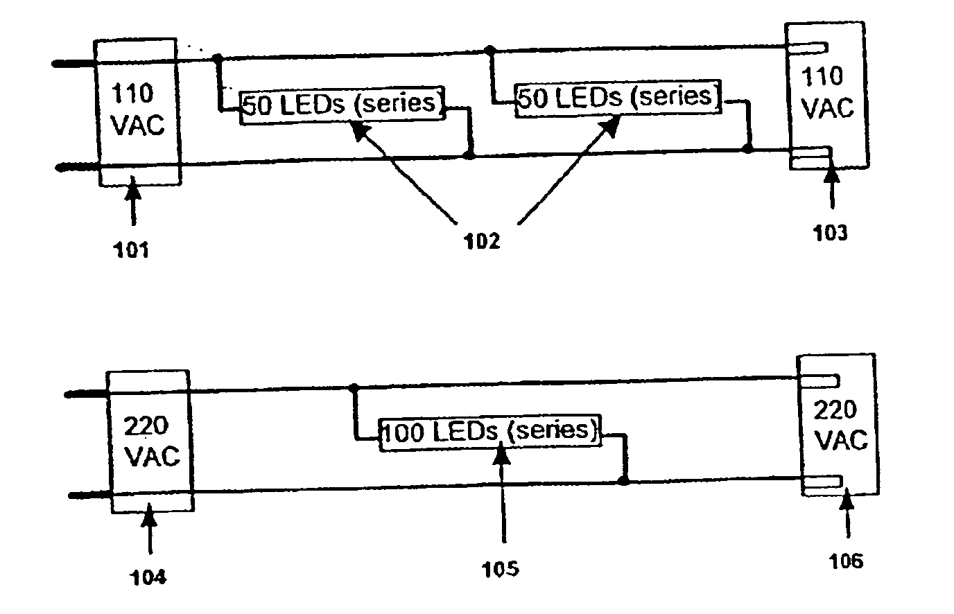
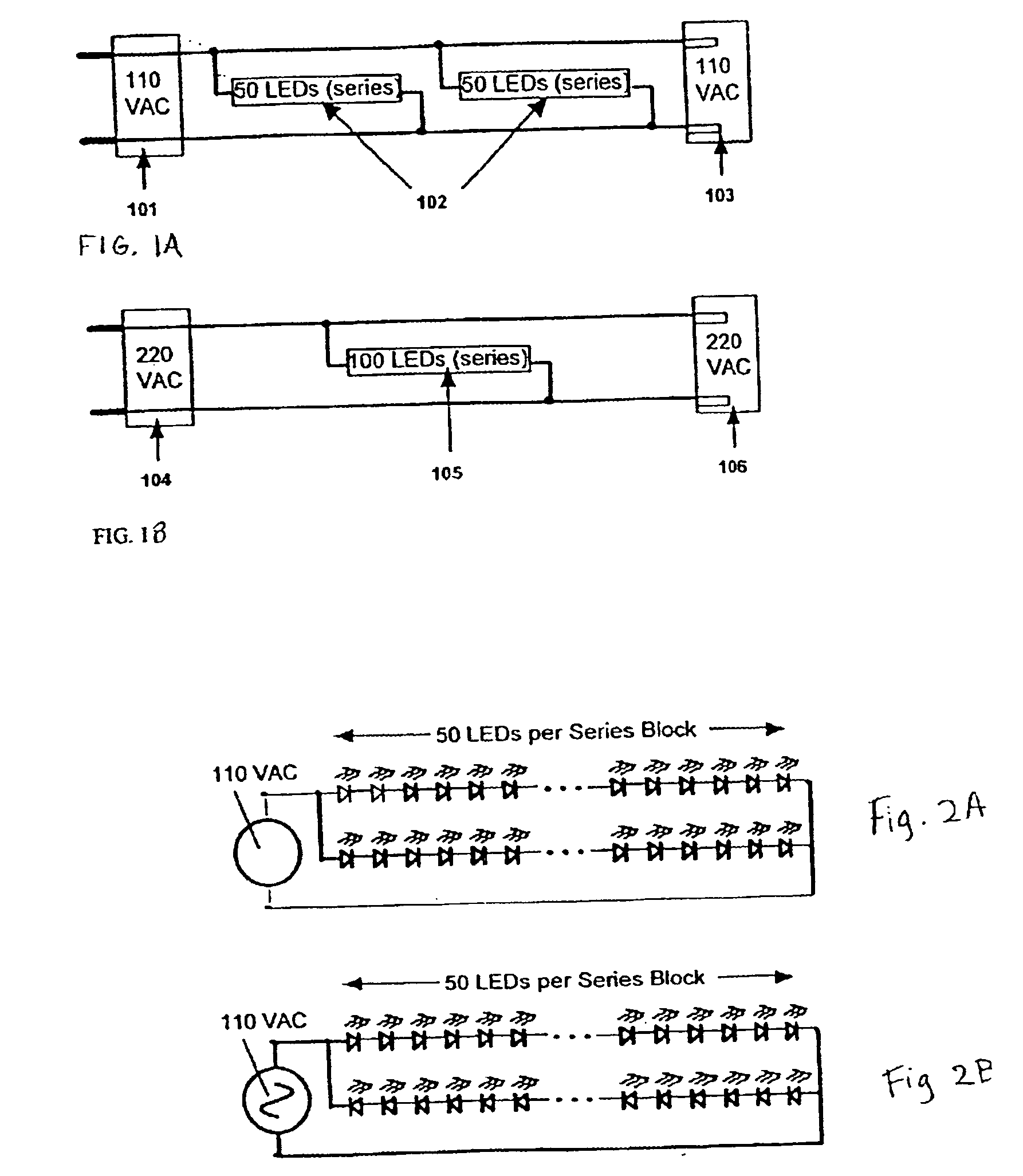
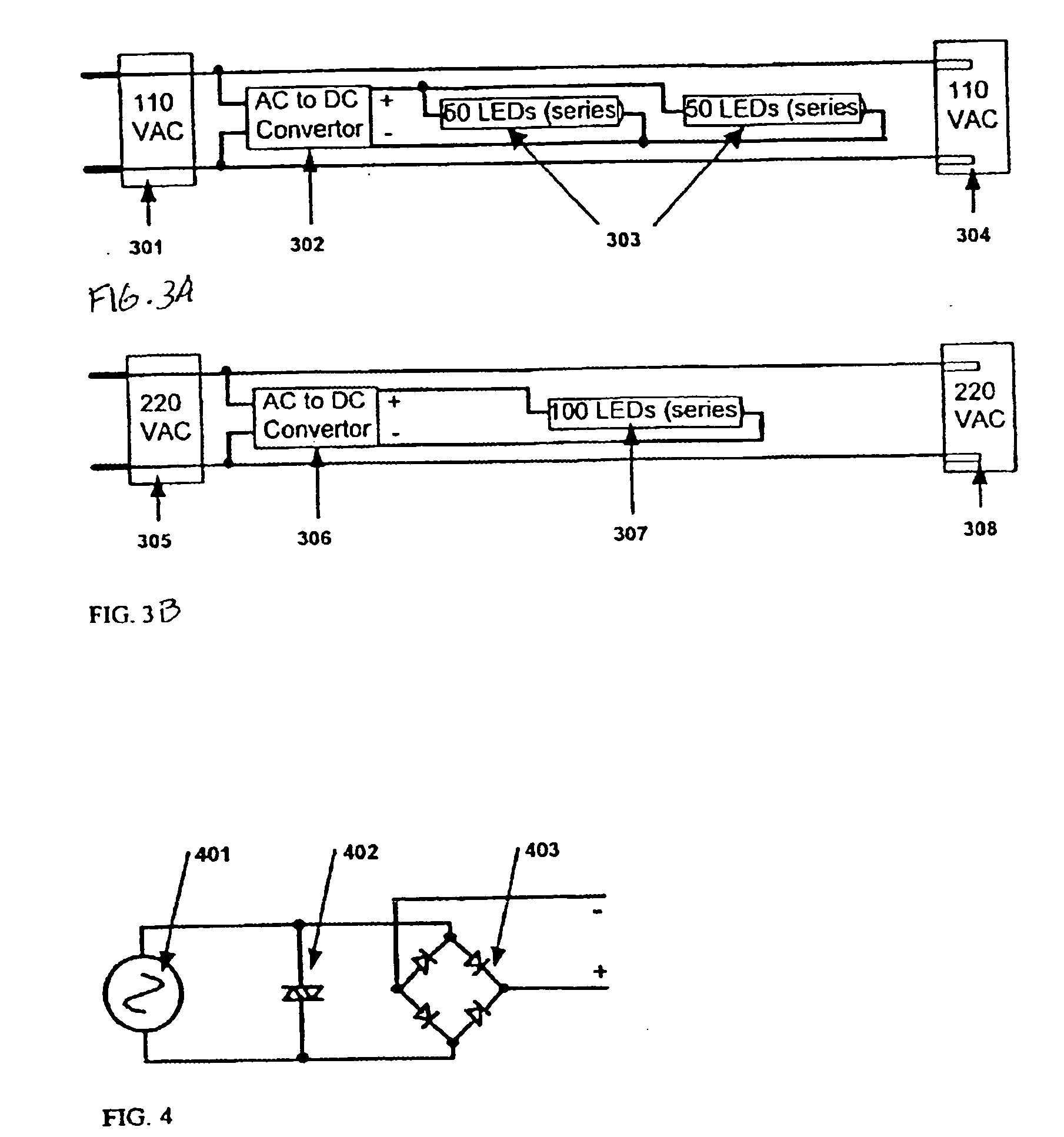
An LED light string employs a plurality of LEDs wired in block series-parallel, where the one or more series blocks, each driven at the same input voltage or rectified AC input voltage as the source voltage (110 VAC or 220 VAC), are coupled in parallel. This voltage matching requirement for direct AC drive places fundamental restrictions on the number of diodes on each diode series block, depending on the types of diodes used. The same method that apply to matching the sum of the LED lamps (VAC values) to the AC input, or applied voltage in an AC circuit apply to matching the sum of the LED lamps (VP values) to the full-wave or half-wave rectified AC (VP) voltage applied. Filtering capacitors may also be employed.

Description

CROSS REFERENCES TO RELATED APPLICATIONS [0001] This application claims benefit under 35 USC §120 from the following co-pending applications: this application is a continuation-in-part of application Ser. No. 10 / 839,335 filed May 06, 2004, which is a continuation-in-part of application Ser. No. 10 / 243,835 filed Sep. 16, 2002, now U.S Pat. No. 6,830,358, which is continuation of application Ser. No. 09 / 819,736 filed Mar. 29, 2001, now U.S. Pat. No. 6,461,019, which is a continuation-in-part of copending application serial number 09 / 339,616 filed Jun. 24, 1999, titled Preferred Embodiment to Led Light String, which is a continuation-in-part of copending application Ser. No. 09 / 141,914 filed Aug. 28, 1998, now U.S. Pat. No. 6,072,280, titled Led Light String Employing Series-parallel Block Coupling, and which is also a non-provisional application claiming benefit under 35 USC ∅(e) of U.S. Provisional Application No. 60 / 119,804, filed Feb. 12, 1999. The disclosures of the aforementioned...

Claims


Application Information

Patent Timeline
Patent Type & Authority Applications(United States)
IPC IPC(8): F21S13/14
CPCF21S4/003F21Y2101/02H05B33/0803H05B33/0809F21S4/20F21Y2115/10H05B45/00
Inventor ALLEN, DAVIDALLEN, MARK R.
Owner FIBER OPTIC DESIGNS
Learn More