Wireless power receiving device, and wireless power transmission device

a technology of wireless power transmission and receiving device, which is applied in the direction of safety/protection circuit, constant-current supply dc circuit, inductance, etc., can solve the problem of increasing the size of the circuit, and achieve the effect of reducing the time delay, preventing the breakage of the circuit element, and restricting the power feeding operation

Active Publication Date: 2015-01-01
TDK CORPARATION
View PDF12 Cites 58 Cited by
  • Summary
  • Abstract
  • Description
  • Claims
  • Application Information

AI Technical Summary

Benefits of technology

[0015]With this configuration, the power-feeding operation controlling means performs the intermittent control action in which start and stop of the power feeding operation of the wireless power feeding device are repeated if the value detected by the power-feeding-side detecting means exceeds the predetermined reference value. Accordingly, it is possible to prevent the breakage of a circuit element, such as the power conversion circuit, even if any abnormality occurs at the power receiving side and the overcurrent flows at the power feeding side. In addition, since the wireless power feeding device itself detects an occurrence of the overcurrent to restrict the power feeding operation in the wireless power transmission device, it is possible to minimize the time delay from the occurrence of any abnormality at the power receiving side to the start of the restriction of the power feeding operation.
[0016]The wireless power receiving device preferably further includes transmitting means that transmits a signal indicating an abnormal state to the wireless power feeding device if the value detected by the power-receiving-side detecting means exceeds the predetermined reference value. If the value detected by the power-feeding-side detecting means exceeds the predetermined reference value and the signal indicating the abnormal state is received from the transmitting means, the power-feeding operation controlling means may stop the power feeding operation of the wireless power feeding device. With the above configuration, since the power feeding operation of the wireless power feeding device is stopped upon detection of any abnormality at the power receiving side, in addition to any abnormality at the power feeding side, it is possible to prevent any problem caused by the stop of the power feeding operation from occurring when the abnormality at the power feeding side is not affected by the abnormality at the power receiving side. As a result, it is possible to improve the reliability as the wireless power transmission device.
[0017]According to the present invention, it is possible to provide a wireless power receiving device and a wireless power transmission device capable of reducing the size of the device and simplifying the device while preventing a circuit element from being broken upon occurrence of any abnormality, such as the overvoltage or the overcurrent.

Problems solved by technology

Accordingly, there is a problem in that the circuit is complicated and the size of the circuit is increased.

Method used


Image

  • Wireless power receiving device, and wireless power transmission device
  • Wireless power receiving device, and wireless power transmission device
  • Wireless power receiving device, and wireless power transmission device

Examples


first embodiment

Modification of First Embodiment

[0051]The configuration of a wireless power transmission device S2, which is a modification of the wireless power transmission device S1 according to the first embodiment of the present invention, will now be descried with reference to FIG. 5. FIG. 5 is a circuit diagram illustrating an exemplary configuration of the wireless power transmission device S2 according to the modification of the first embodiment of the present invention with the load.

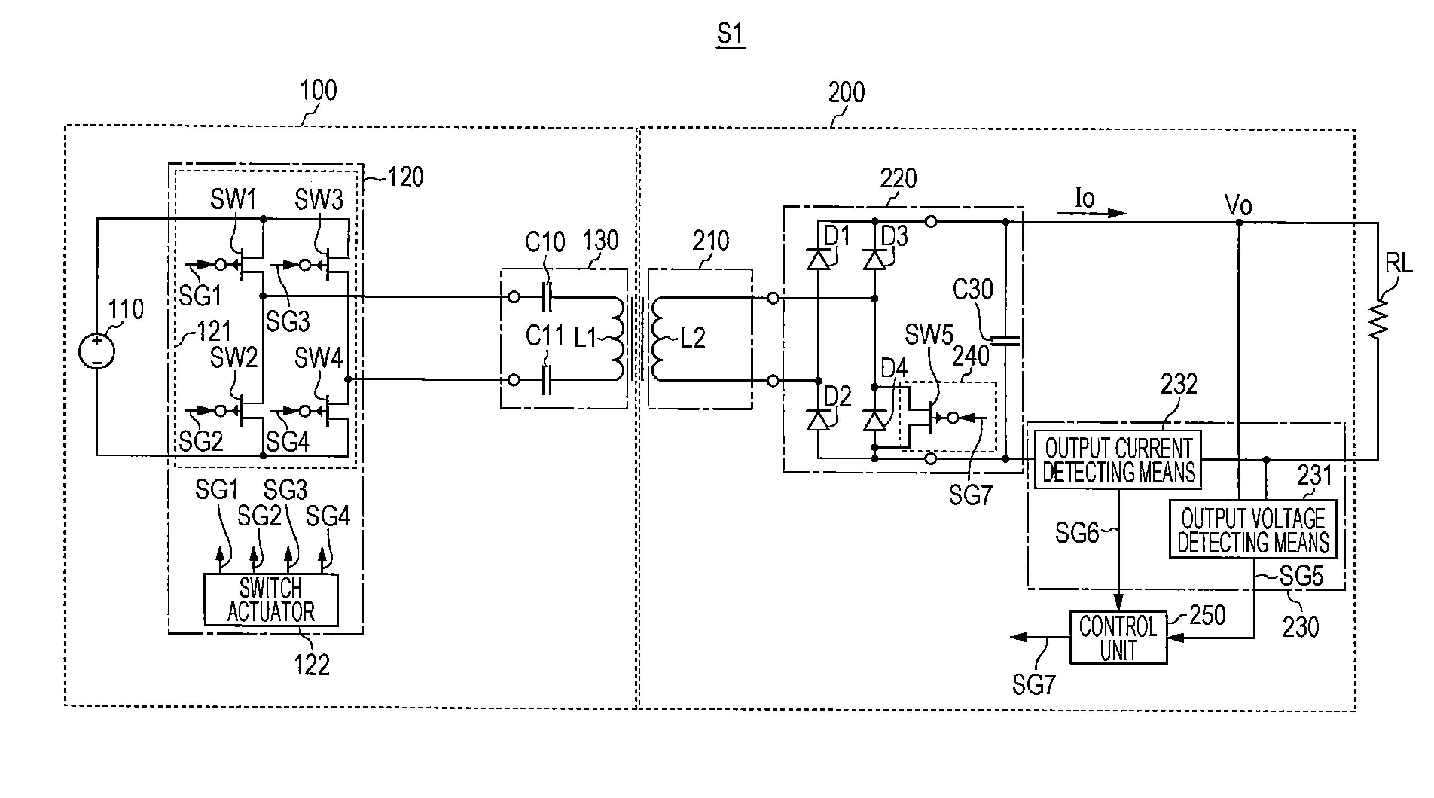
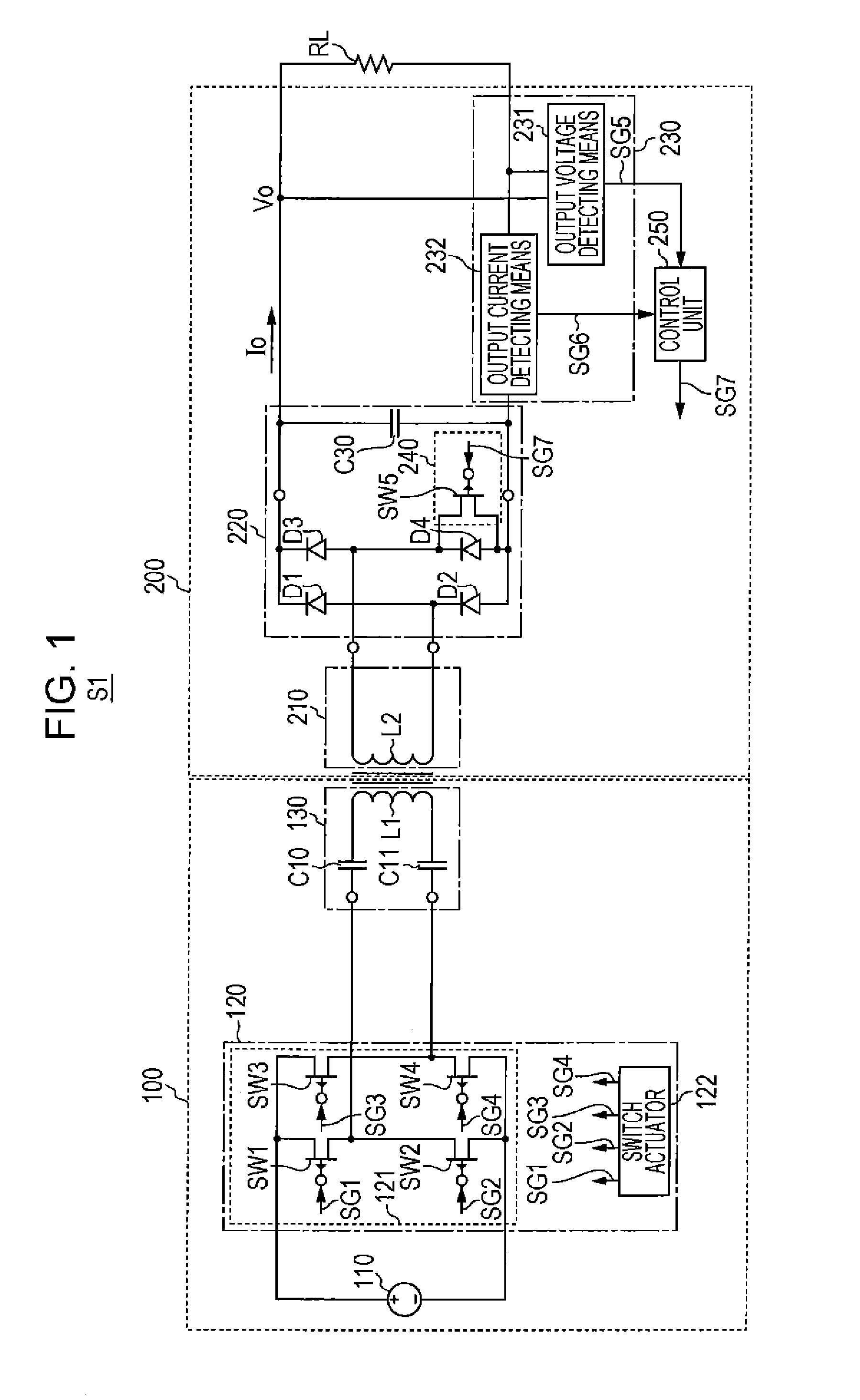
[0052]Referring to FIG. 5, the wireless power transmission device S2 includes the wireless power feeding device 100 and the wireless power receiving device 200. The wireless power feeding device 100 includes the power source 110, the power conversion circuit 120, and the power feeding unit 130. The wireless power receiving device 200 includes the power receiving unit 210, a rectifier unit 320, the power-receiving-side detecting means 230, switching means 340, and a control unit 350. The configurations of the p...

second embodiment

[0057]The configuration of a wireless power transmission device S3 according to a second embodiment of the present invention will now be descried with reference to FIG. 6. FIG. 6 is a circuit diagram illustrating an exemplary configuration of the wireless power transmission device S3 according to the second embodiment of the present invention with the load.

[0058]Referring to FIG. 6, the wireless power transmission device S3 includes the wireless power feeding device 100 and the wireless power receiving device 200, as in the wireless power transmission device S1 according to the first embodiment. The wireless power feeding device 100 includes the power source 110, the power conversion circuit 120, the power feeding unit 130, power-feeding-side detecting means 440, receiving means 450, and power-feeding operation controlling means 460, as illustrated in FIG. 6. The configurations of the power source 110, the power conversion circuit 120, and the power feeding unit 130 are the same as ...

third embodiment

[0070]The configuration of a wireless power transmission device S4 according to a third embodiment of the present invention will now be descried with reference to FIG. 7. FIG. 7 is a circuit diagram illustrating an exemplary configuration of the wireless power transmission device S4 according to the third embodiment of the present invention with the load.

[0071]Referring to FIG. 7, the wireless power transmission device S4 includes the wireless power feeding device 100 and the wireless power receiving device 200, as in the wireless power transmission device S1 according to the first embodiment. The wireless power feeding device 100 includes the power source 110, the power conversion circuit 120, and the power feeding unit 130, as illustrated in FIG. 7. The wireless power receiving device 200 includes a power receiving unit 310, the rectifier unit 220, the power-receiving-side detecting means 230, the switching means 240, and the control unit 250, as illustrated in FIG. 7. The configu...


PUM


Abstract

To provide a wireless power receiving device, and a wireless power transmission device capable of improving the reliability of a protection circuit while preventing breakage of a circuit element upon occurrence of any abnormality, such as overvoltage or overcurrent. A wireless power receiving device includes a power receiving coil; a rectifier unit that performs full-wave rectification of the power received by the power receiving coil and supplies the power to a load; power-receiving-side detecting unit that detects an output voltage value or an output current value from the rectifier unit; and switching unit that short-circuits one of two current paths through the rectifier unit if the value detected by the power-receiving-side detecting unit exceeds a predetermined reference value.

Description

BACKGROUND OF THE INVENTION[0001]1. Field of the Invention[0002]The present invention relates to a wireless power receiving device and a wireless power transmission device.[0003]2. Description of the Related Art[0004]In recent years, attention is paid to a wireless power transmission technology to externally supply power in a wireless mode without using a power cable in electric vehicles and mobile devices.[0005]Since an occurrence of any abnormality in transmission of high power may cause breakage of a circuit element, such as a load, in such a wireless power transmission technology, there is an increasing demand to improve the safety of the entire device to which the wireless power transmission technology is applied.[0006]In response to such a demand, for example, Japanese Unexamined Patent Application Publication No. 11-27870 proposes a charging device including an inverter circuit, a rectifier circuit, a booster circuit, a voltage checking circuit, and a short-circuiting circuit...

Claims


Application Information

Patent Timeline
Patent Type & Authority Applications(United States)
IPC IPC(8): H04B5/00
CPCH04B5/0037H02J7/025H04B5/0075H02J1/04H02J1/002H02J7/0029H02J50/80H02J50/90H02J50/12
Inventor SAEN, TSUNEHIROOHNISHI, MASAHIDEMIYAZAWA, RYO
Owner TDK CORPARATION
Why Eureka
Try Eureka