High efficiency, multi-source photovoltaic inverter

a photovoltaic inverter, multi-source technology, applied in the direction of dc-dc conversion, dc-dc conversion, dc-ac conversion without reversal, etc., can solve the problems of overall switching loss, one-half system loss, undetected control of power circuit, etc., to increase the level of voltage sourcing

Active Publication Date: 2009-12-03
GENERAL ELECTRIC CO
View PDF9 Cites 61 Cited by
  • Summary
  • Abstract
  • Description
  • Claims
  • Application Information

AI Technical Summary

Benefits of technology

[0015]According to yet another embodiment of the invention, a photovoltaic (PV) inverter system is configured to continuously operate in a buck converter mode to generate a sum of full wave rectified sine wave currents at a current node common to a plurality of buck converters in response to a plurality of full wave rectified sine wave currents generated via the plurality of buck converters, and is further configured to increase the level of the voltage sourcing each buck converter, via a corresponding boost converter, when a corresponding DC power source voltage is lower than the instantaneous voltage of a utility grid connected to the PV inverter system.

Problems solved by technology

The efficiency of the two-stage inverter is an important parameter affecting PV system performance and is a multiple of the individual stage efficiencies with each stage typically causing one-half of the system losses.
Traditional single phase PV inverters also undesirably control the power circuits with a fixed switching frequency using a plurality i.e. five, of switching devices that contribute to the overall switching losses.

Method used


Image

  • High efficiency, multi-source photovoltaic inverter
  • High efficiency, multi-source photovoltaic inverter
  • High efficiency, multi-source photovoltaic inverter

Examples


Embodiment Construction

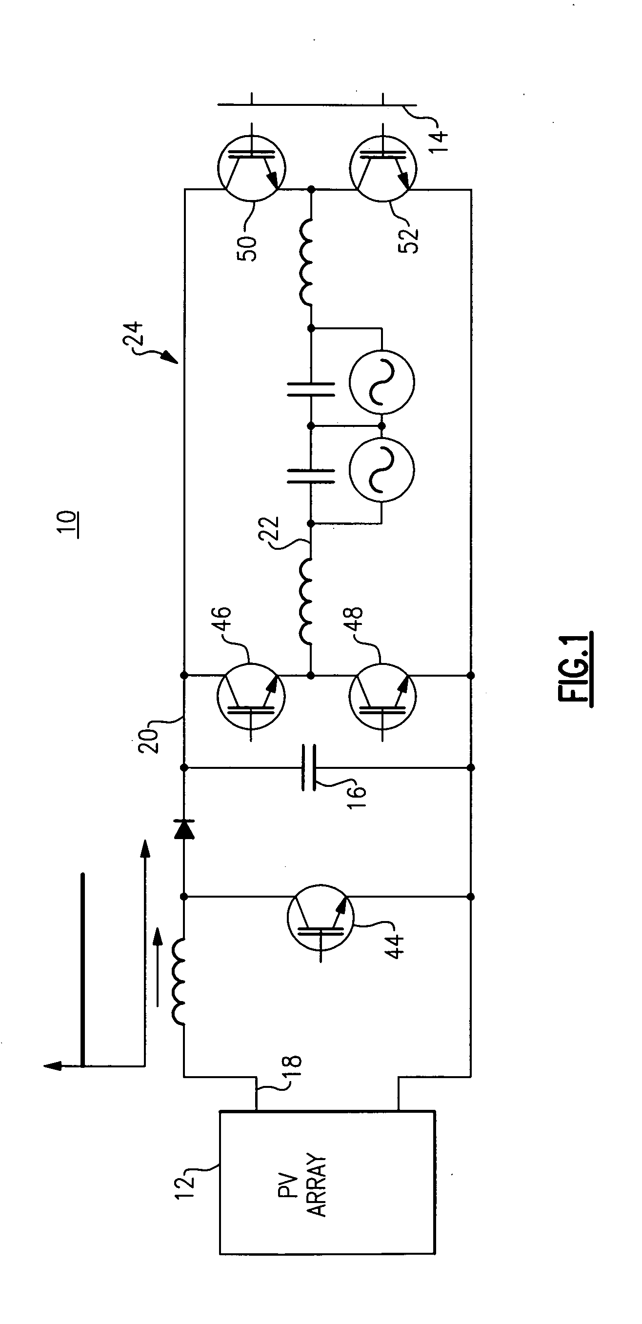
[0028]FIG. 1 is illustrates a photovoltaic inverter 10 topology that is known in the art. Photovoltaic inverter 10 employs a two-stage power circuit to convert a varying DC voltage of a PV array 12 to a fixed frequency AC current for a power grid 14. Photovoltaic inverter 10 uses a DC link capacitor 16 to implement the intermediate energy storage step. This means the PV inverter 10 first converts the unstable PV DC voltage 18 to a stable DC voltage 20 that is greater than the grid voltage via a boost converter, and subsequently converts the stable DC voltage 20 to a current 22 via a PWM circuit 24 that can then be injected into the grid 14. Photovoltaic inverter 10 topology employs five switching devices 44, 46, 48, 50, 52 that are all switching at a high frequency and that undesirably contribute to the overall switching losses of the two-stage converter.

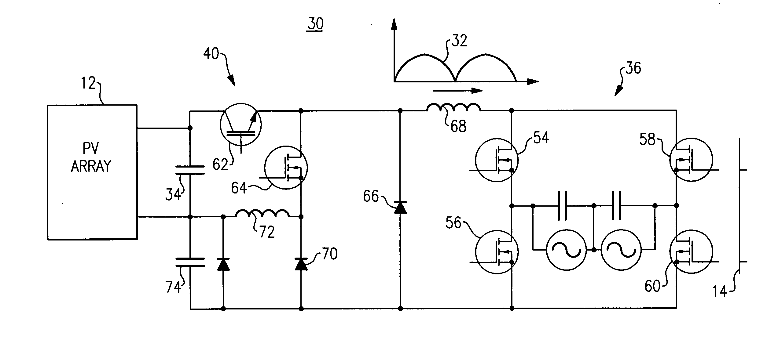
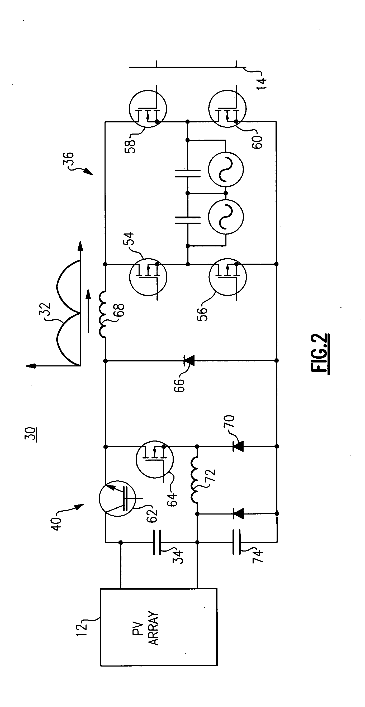
[0029]FIG. 2 illustrates a photovoltaic inverter 30 hard-switching topology according to one embodiment of the invention. Photovol...


PUM


Abstract

A photovoltaic (PV) inverter system operates continuously in a buck converter mode to generate a sum of full wave rectified sine wave currents at a current node common to a plurality of buck converters in response to a plurality of full wave rectified sine wave currents generated via the plurality of buck converters. The PV inverter system increases the level of the voltage sourcing each buck converter when a corresponding DC power source voltage is lower than the instantaneous voltage of a utility grid connected to the PV inverter system.

Description

BACKGROUND[0001]The invention relates generally to electronic power conversion and more particularly to a very high conversion efficiency, grid connected, single phase, multi-source photovoltaic (PV) inverter.[0002]Photovoltaic (PV) cells generate direct current (DC) power with the level of DC current being dependent on solar irradiation and the level of DC voltage dependent on temperature. When alternating current (AC) power is desired, an inverter is used to convert the DC energy into AC energy. Typical PV inverters employ two stages for power processing with the first stage configured for providing a constant DC voltage and the second stage configured for converting the constant DC voltage to AC current. Often, the first stage includes a boost converter, and the second stage includes a single-phase or three-phase inverter system. The efficiency of the two-stage inverter is an important parameter affecting PV system performance and is a multiple of the individual stage efficiencie...

Claims


Application Information

Patent Timeline
Patent Type & Authority Applications(United States)
IPC IPC(8): H02M7/48
CPCH02M3/1588H02M3/3374H02M2001/007Y02E10/56Y02B70/1433Y02B70/1466Y02B70/1425H02M7/53871H02J2300/24H02J3/381Y02B70/10H02M1/0054H02M1/007H02M1/0093
Inventor DE ROOIJ, MICHAEL ANDREWGLASER, JOHN STANLEY
Owner GENERAL ELECTRIC CO
Why Eureka
Try Eureka