Rotary electric system with star-connected multiphase stator windings

a technology of multi-phase stator windings and rotary electric systems, which is applied in the direction of special data processing applications, emergency protective arrangements for automatic disconnection, electric devices, etc., can solve the problems of increasing the size and/or manufacturing cost reducing the installationability of electric power steering systems in various vehicles and machines, and reducing the drivability of three-phase brushless motors. , to achieve the effect of reducing current unbalance, reducing torque rippl

Active Publication Date: 2009-04-16
DENSO CORP
View PDF9 Cites 59 Cited by
  • Summary
  • Abstract
  • Description
  • Claims
  • Application Information

AI Technical Summary

Benefits of technology

[0015]It is therefore possible to drive the multiphase stator windings to thereby continuously rotate the rotor even though at least one high-side switching element of the multiphase inverter fails without using switches for the respective multiphase stator windings.
[0016]This achieves an effect of reliably addressing an open fault occurring in at least one high-side switching element of the multiphase inverter with the circuit structure of the rotary

Problems solved by technology

This results in reducing the drivability of the three-phase brushless motor.
In addition, the electric power steering system disclosed in the Patent Application Publication may have a complicated circuit structure that individually turns off a power semiconductor switchi

Method used


Image

  • Rotary electric system with star-connected multiphase stator windings
  • Rotary electric system with star-connected multiphase stator windings
  • Rotary electric system with star-connected multiphase stator windings

Examples


Embodiment Construction

[0028]An embodiment of the present invention will be described hereinafter with reference to the accompanying drawings.

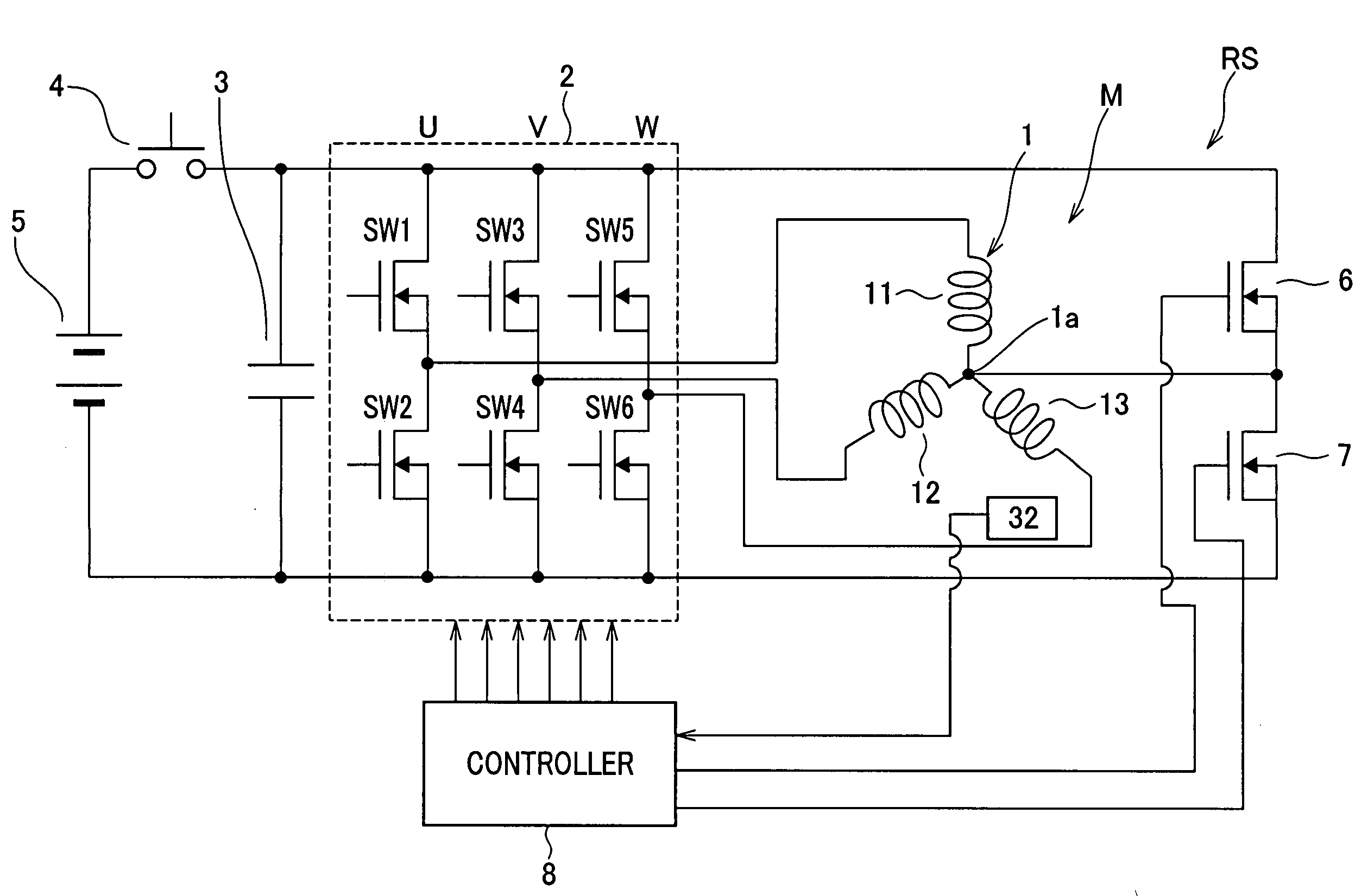
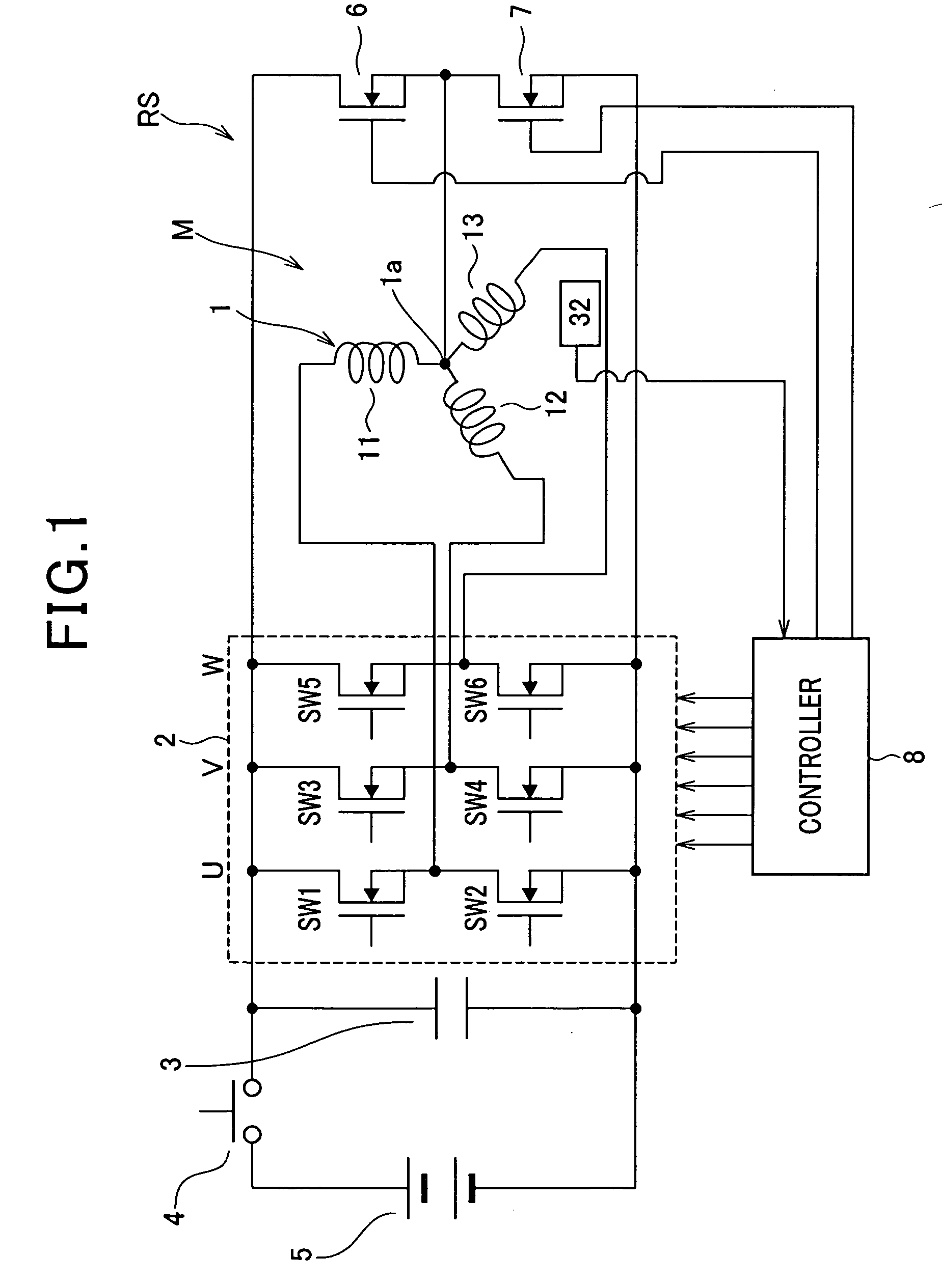
[0029]Referring to FIG. 1, there is provided a rotary electric system RS according to an embodiment of the present invention.

[0030]The rotary electric system RS includes a three-phase motor M equipped with an annular rotor (not shown) and a star-connected three-phase stator coil 1. The annular rotor is provided at its circumferential portion with at least one north pole (N) and at least one south pole (S).

[0031]The rotary electric system RS also includes a three-phase inverter 2 for supplying three-phase AC power to the three-phase stator coil 1, and a smoothing capacitor 3 operative to smooth an input DC voltage to be inputted to the inverter 2.

[0032]The stator coil 1 consists of a stator core (not shown) disposed around the outer periphery of the rotor such that the inner periphery of the stator core is opposite to the outer periphery of the rotor with a predeterm...


PUM


Abstract

In a rotary electric system, a switch member includes at least one of a first switch and a second switch. The first switch is connected between a neutral point of multiphase stator windings and a high-side electrode of a direct current power source. The second switch is connected between the neutral point and a low-side electrode of the direct current power source. A controller works to turn the switch member off and on thereby switching control of the multiphase inverter between full-wave driving mode and half-wave driving mode. The full-wave driving mode allows the controller to drive all of the high-side and low-side switching elements per phase of the multiphase stator windings. The half-wave driving mode allows the controller to drive any one of the high-side switching element and the low-side switching element per phase of the multiphase stator windings.

Description

CROSS REFERENCE TO RELATED APPLICATIONS[0001]This application is based on Japanese Patent Application 2007-264743 filed on Oct. 10, 2007. The descriptions of the Patent Application are all incorporated herein by reference.FIELD OF THE INVENTION[0002]The present invention relates to a rotary electric system equipped with a multiphase inverter including a pair of high-side and low-side switching elements for each phase of a multiphase motor, and more particularly to such a rotary electric system designed to address a fault, such as an open fault, of at least one switching element constituting the inverter.BACKGROUND OF THE INVENTION[0003]Alternating current (AC) motor systems are used widely for: motor vehicles as their electric power steering systems, hybrid vehicles as their drive systems, and electric compressors as their drive systems. Such an AC motor system is designed to drive a multiphase motor having a multiphase stator coil by a multiphase inverter; this multiphase stator co...

Claims


Application Information

Patent Timeline
IPC IPC(8): H02P6/12H02P21/00H02P27/04H02P21/22H02P29/00
CPCH02M1/32H02P2209/01H02P29/022B60L3/003H02P29/032Y02T10/64
Inventor TANIGUCHI, MAKOTO
Owner DENSO CORP
Why Eureka
Try Eureka