
Video recording apparatus and method thereof

Inactive Publication Date: 2007-06-07
PIONEER CORP
View PDF0 Cites 7 Cited by
  • Summary
  • Abstract
  • Description
  • Claims
  • Application Information

AI Technical Summary

Benefits of technology

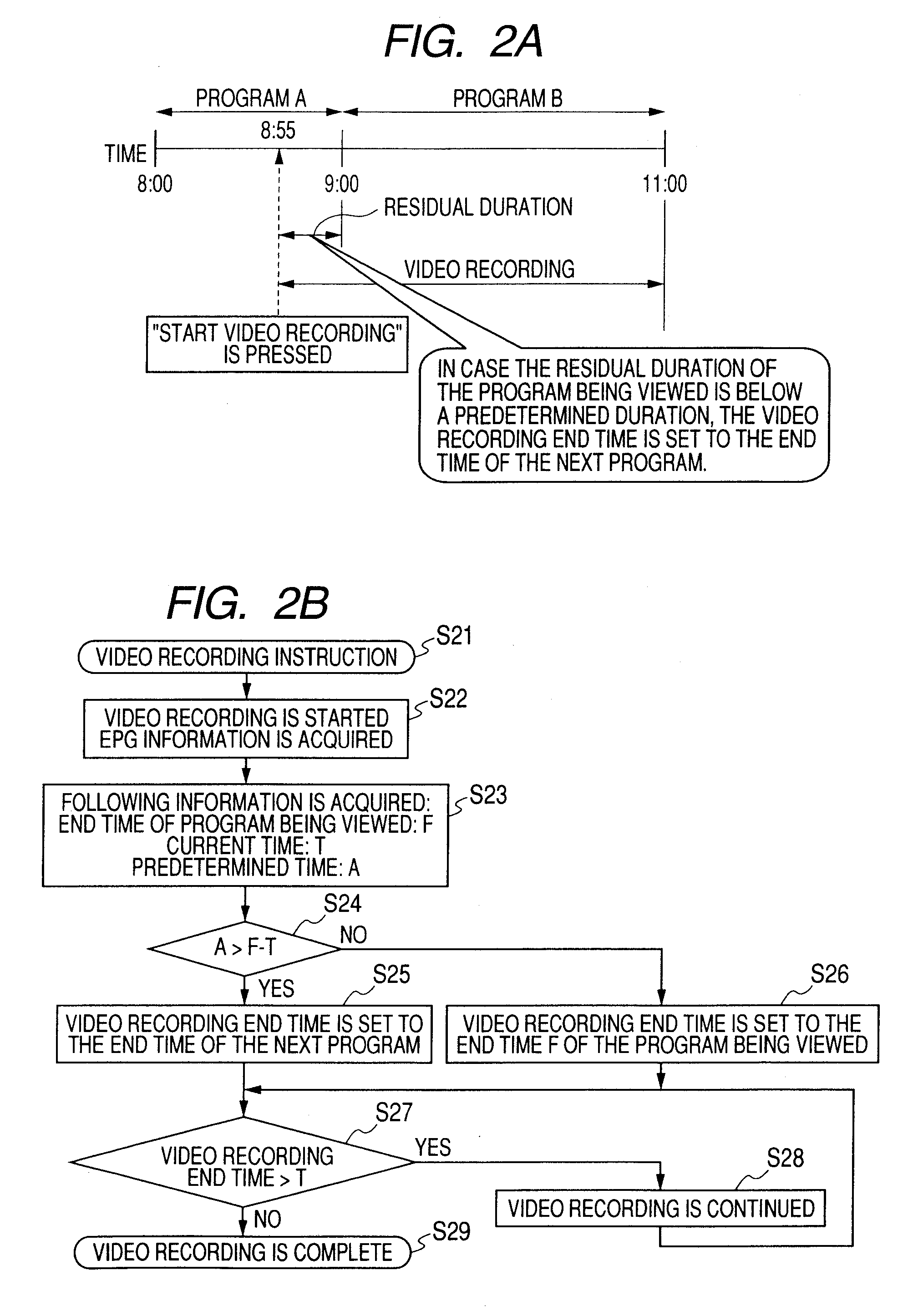
[0005] According to another aspect of the invention, there is provided a video recording apparatus comprising: a tuner unit receiving a program broadcast; a signal separation unit separating, respectively, video, an audio signal, an EPG program information signal and a time signal from the program broadcast signal of a channel received by the tuner unit; a video recording unit recording a video/audio signal separated by the signal separation unit; an input unit with which a user manually instructs a start of recording on the video recording unit; a program end time detection unit detecting from the EPG program information signal an end time of the broadcast program for which the start of recording is instructed with the input unit; a preselected video recording duration calculation unit calculating a preselected video recording duration from a recording start time at which the start of the recording is instructed to the end time of the broadcast program; a video recording end time setting unit, by comparing the preselected video recording duration with a preset reference video recording duration, assuming a video recording end time as an end time of a broadcast program next to the broadcast program for which the start of video recording is instructed in case that the preselected video recording duration is shorter than the preset reference video recording duration and assuming the video recording end time as the end time of the broadcast program for which the start of video recording is instructed in case that the preselected video recording duration is longer than the preset reference video recording duration; and a video recording control unit controlling to stop the video recording unit at the time

Problems solved by technology

This prevents video recording of a desired broadcast program.

Method used


Image

  • Video recording apparatus and method thereof
  • Video recording apparatus and method thereof
  • Video recording apparatus and method thereof

Examples


embodiment 1

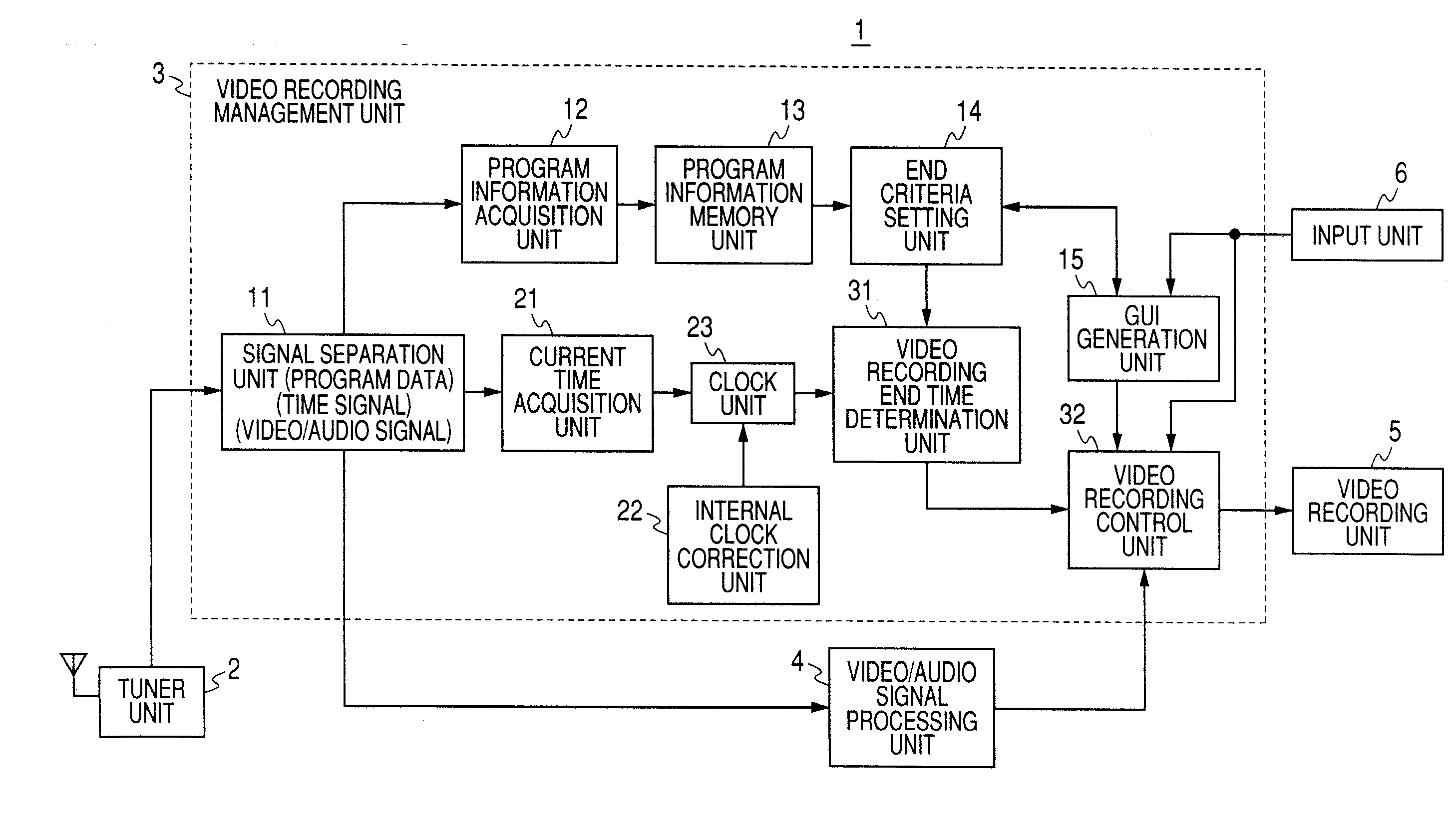
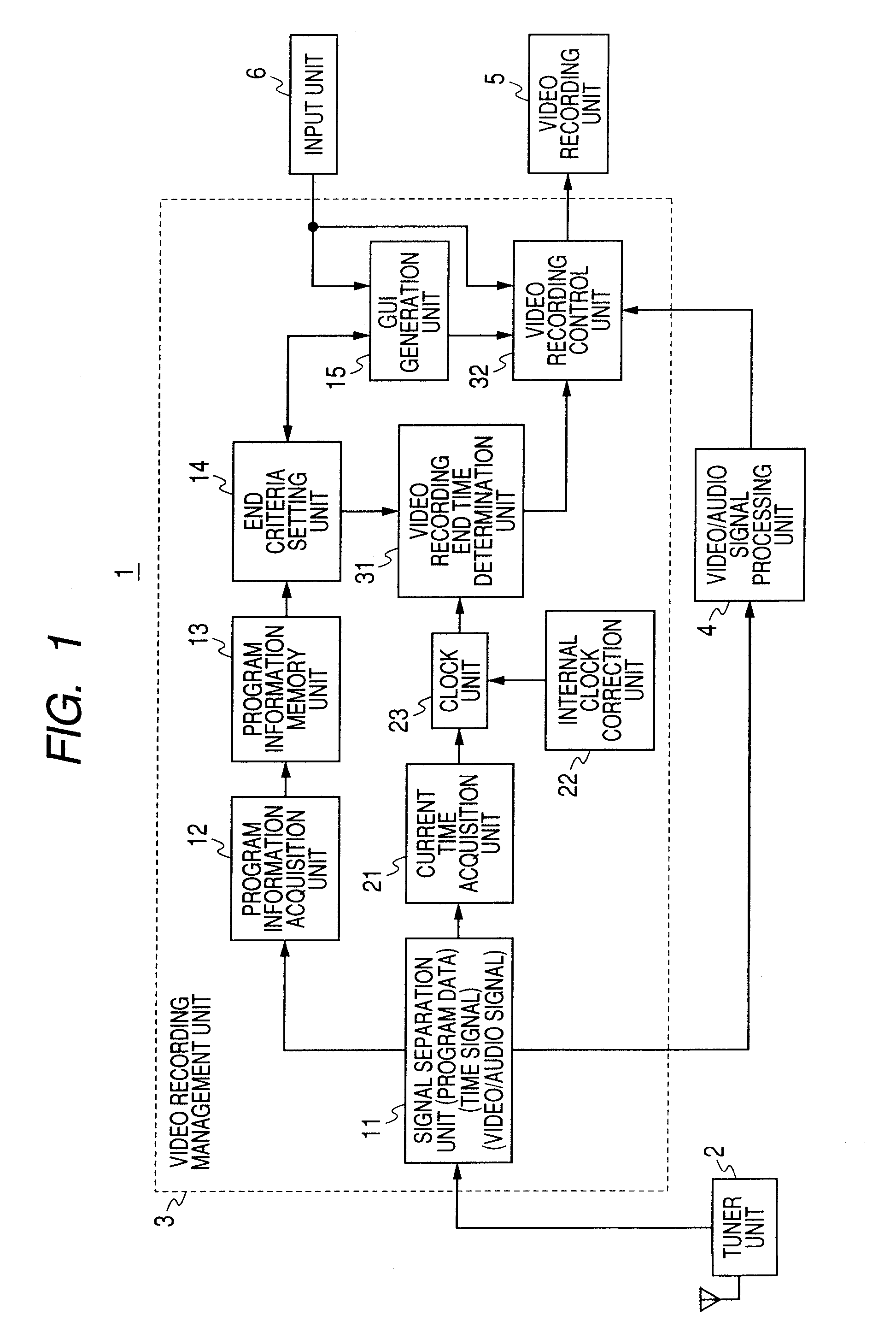
[0017]FIG. 1 is a block diagram showing the configuration of an embodiment of the invention.

[0018] Video recording apparatus 1 comprises a tuner unit 2 for receiving a program broadcast signal, a video recording information management unit 3 for managing information on video. recording, a video / audio signal processing unit 4 for acquiring the video and audio signals of a video recording target, a video recording unit 5 for recording the acquired video and audio signals, and an input unit 6 the use operates to input data.

[0019] The video recording information management unit 3 includes a signal separation unit 11 for inputting a receive signal output from the tuner unit 2 and separating program data, a time signal, a video signal and an audio signal, program information acquisition unit 12 for processing the separated program data, a program information memory unit 13, an end criteria setting unit 14, a GUI generation unit 15 for generating the screen data of this setting, a curren...

embodiment 2

[0033] The second embodiment will be explained referring to FIGS. 1 and 3B.

[0034] The configuration of the second embodiment is similar to that shown in the block diagram of FIG. 1, except that setting of criteria on the end criteria setting unit 14 and the video recording end time determination unit 31.

[0035] As shown in the time chart of FIG. 3A, the user manually instructs the start of video recording on the input unit before the start of Program B in order to perform video recording of the entire program B on the video recording apparatus 1. For example, as shown in FIG. 3A, the user instructs the “start of video recording” to the video recording apparatus 1 in the midst of Program A on the air before the target program at the time 8:55 (step S31).

[0036] In response to the start instruction, same as the first embodiment, the signal separation unit 11 of the video recording apparatus 1 receiving the broadcast program A on the tuner unit 2 separates the video / audio signal from ...

embodiment 3

[0044] The third embodiment will be described referring to FIGS. 4A, 4B.

[0045] The configuration of the third embodiment is similar to that of the first or second embodiment as shown in the block configuration of FIG. 1. In this embodiment, the end criteria setting unit 14 and the video recording end time determination unit 31 operate as shown in the flowchart of FIG. 4B.

[0046] Processing by the end criteria setting unit 14 and the video recording end time determination unit 31 made in the third embodiment starts with a video recording instruction (step S41). Next, as shown in the time chart of FIG. 4A, Broadcast Program A is received and a video / audio signal, an EPG information signal and a time signal are separated and video recording is started (step S42).

[0047] The program end time F (F=S+D) calculated from the program start time S and the program length D in the EPG information signal is acquired, and the predetermined specific determination duration A defaulted by the GUI g...


PUM


Abstract

A video recording apparatus, by comparing the preselected video recording duration with a preset reference video recording duration, assumes a video recording end time as an end time of a broadcast program next to the broadcast program for which the start of video recording is instructed in case the preselected video recording duration is shorter than the preset reference video recording duration, and assumes the video recording end time as the end time of the broadcast program for which the start of video recording is instructed in case that the preselected video recording duration is longer than the preset reference video recording duration.

Description

TECHNICAL FIELD [0001] The present invention relates to a video recording apparatus recording a broadcast program. DESCRIPTION OF THE RELATED ART [0002] Generally speaking, in case video recording of a television broadcast program is reserved, a video recording start time and end time are respectively set on video recording apparatus. Recently, a program reservation method is in widespread use that uses EPG (Electronic Program Guide) information transmitted in multiplexed form on television broadcast radio waves. As one of the methods that use the EPG information, a so-called one-touch video recording method is known where video recording is started based on a video recording instruction manually made by the user (viewer, operator) and video recording is automatically terminated at an end time from EPG information (for example, refer to Japanese Patent No. 3530454 (first half of the paragraph [0009])). [0003] According to this method, the EPG information of a broadcast program of wh...

Claims


Application Information

Patent Timeline
IPC IPC(8): H04N5/91
CPCH04N5/76
Inventor YAMADA, AKIHITOMURAYAMA, MASAYOSHI
Owner PIONEER CORP
Learn More