
Biomorphic rhythmic movement controller

a rhythmic movement and controller technology, applied in the field of robotics and movement control, can solve the problems of not being able to respond to or adapt based on sensory input, their system is not a robotic system, and no motoneuron output stage, etc., and achieve the effect of sophisticated responsiveness and adaptability

Inactive Publication Date: 2007-06-07
ETIENNE CUMMINGS RALPH +1
View PDF5 Cites 8 Cited by
  • Summary
  • Abstract
  • Description
  • Claims
  • Application Information

AI Technical Summary

Benefits of technology

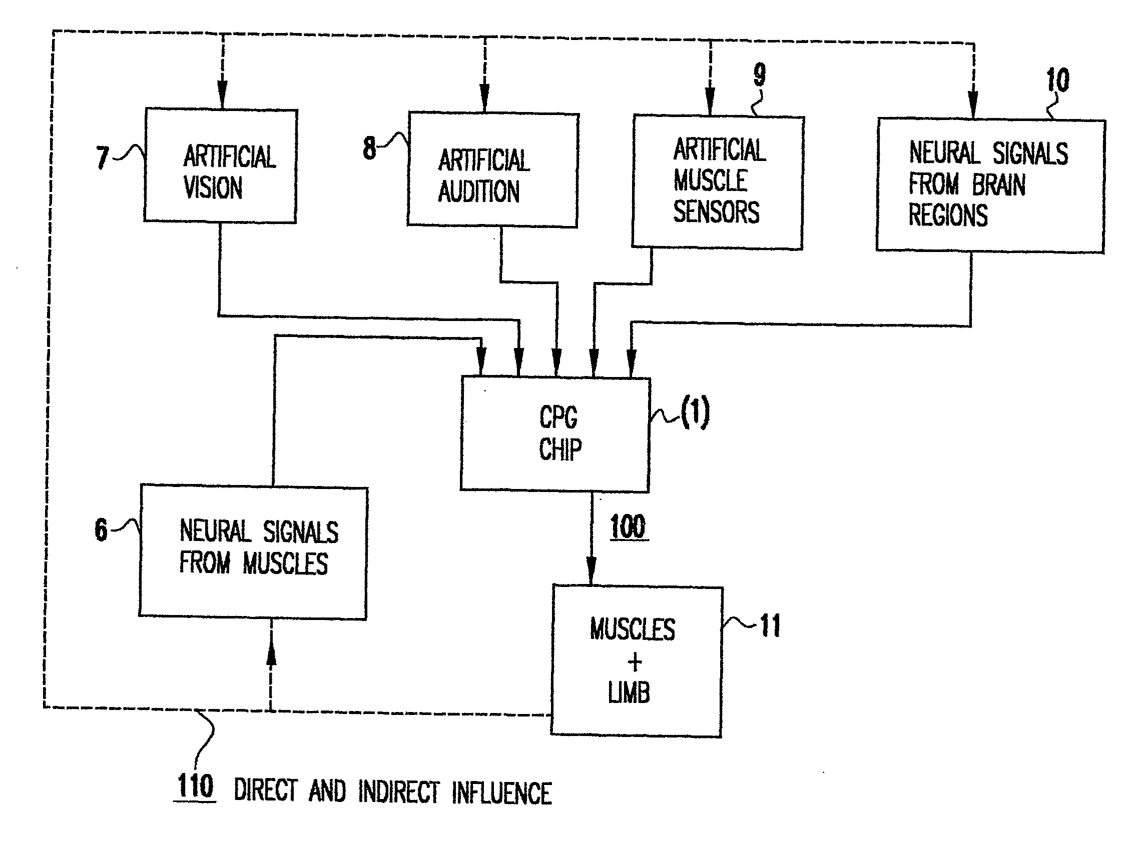
"The present invention provides a CPG-based system that can adapt and respond to its environment, making it suitable for use in biological and non-biological applications. The system can control the movement of mechanical and biological systems using a non-biological CPG chip. It can also include advanced features such as phase adjustment and responsiveness to sensory feedback. The invention also provides a system for rhythmic movement control and a chip that contains electronic analogues of biological neurons, synapses, and time-constraints. The CPG-based system can be a non-linear oscillator or a distributed system of non-linear oscillators. It can also include at least one sensor for collecting sensory feedback. Overall, the invention provides a flexible and adaptable platform for controlling movement and behavior in biological and non-biological systems."

Problems solved by technology

However, Still's system has no motoneuron output stage, and cannot respond to or adapt based on sensory input.
Their system is not a robotic system and cannot respond to or use feedback from sensors.
This system of DeWeerth's cannot easily be applied to control a robot, primarily because parameter sensitivity makes such circuits difficult to tune.
The adapted DeWeerth system, however, is not adaptive and does not use external inputs from sensors.
's neural-based approach, using software, is relatively basic and does not teach, for example, VLSI implementation, self-adaptation to an environment, low-power compact implementation using one chip, or silicon learning.
Such systems have limitations, such as being unable to provide self-adaptive features.

Method used


Image

  • Biomorphic rhythmic movement controller
  • Biomorphic rhythmic movement controller
  • Biomorphic rhythmic movement controller

Examples


example no.1

EXAMPLE NO. 1

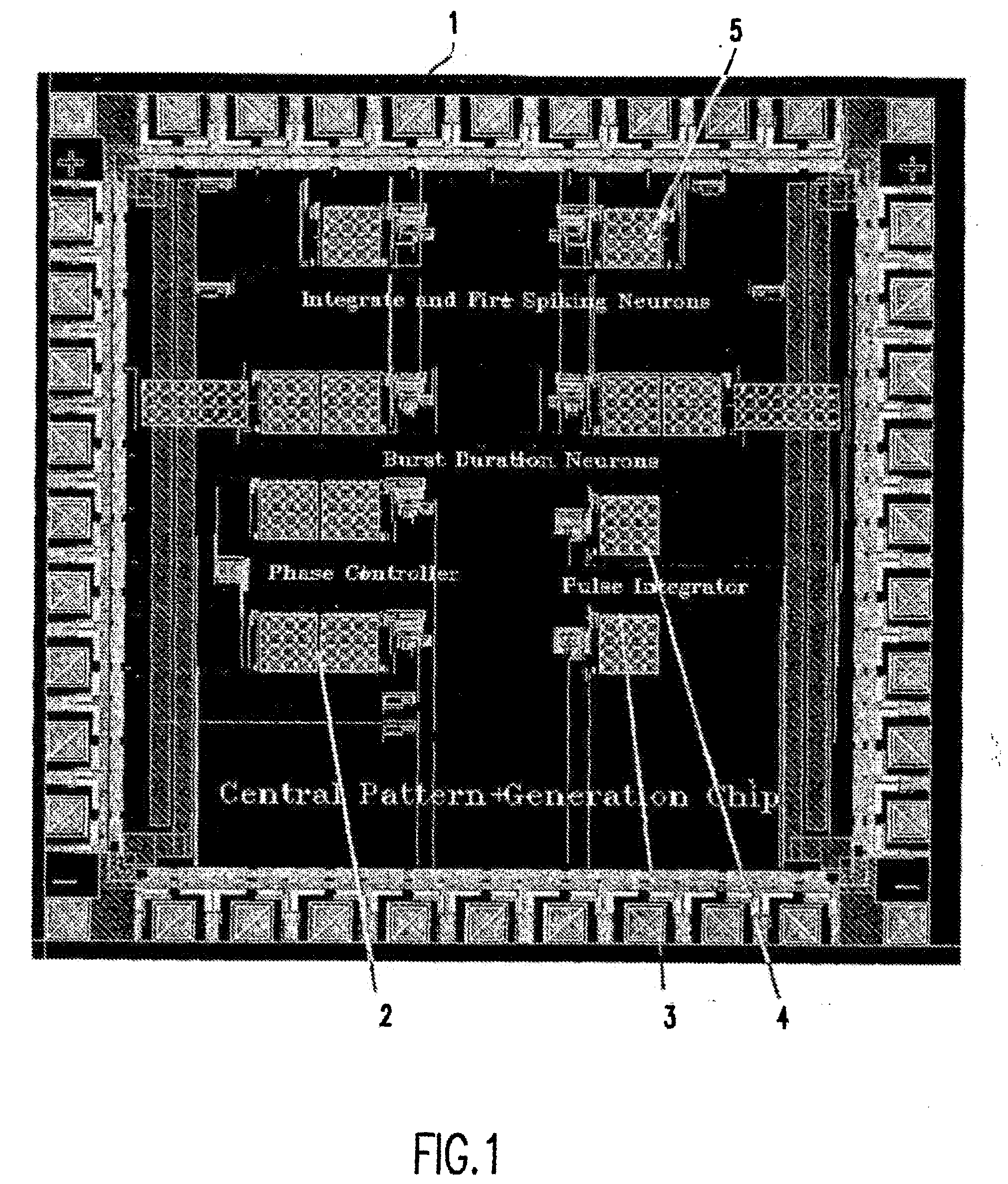
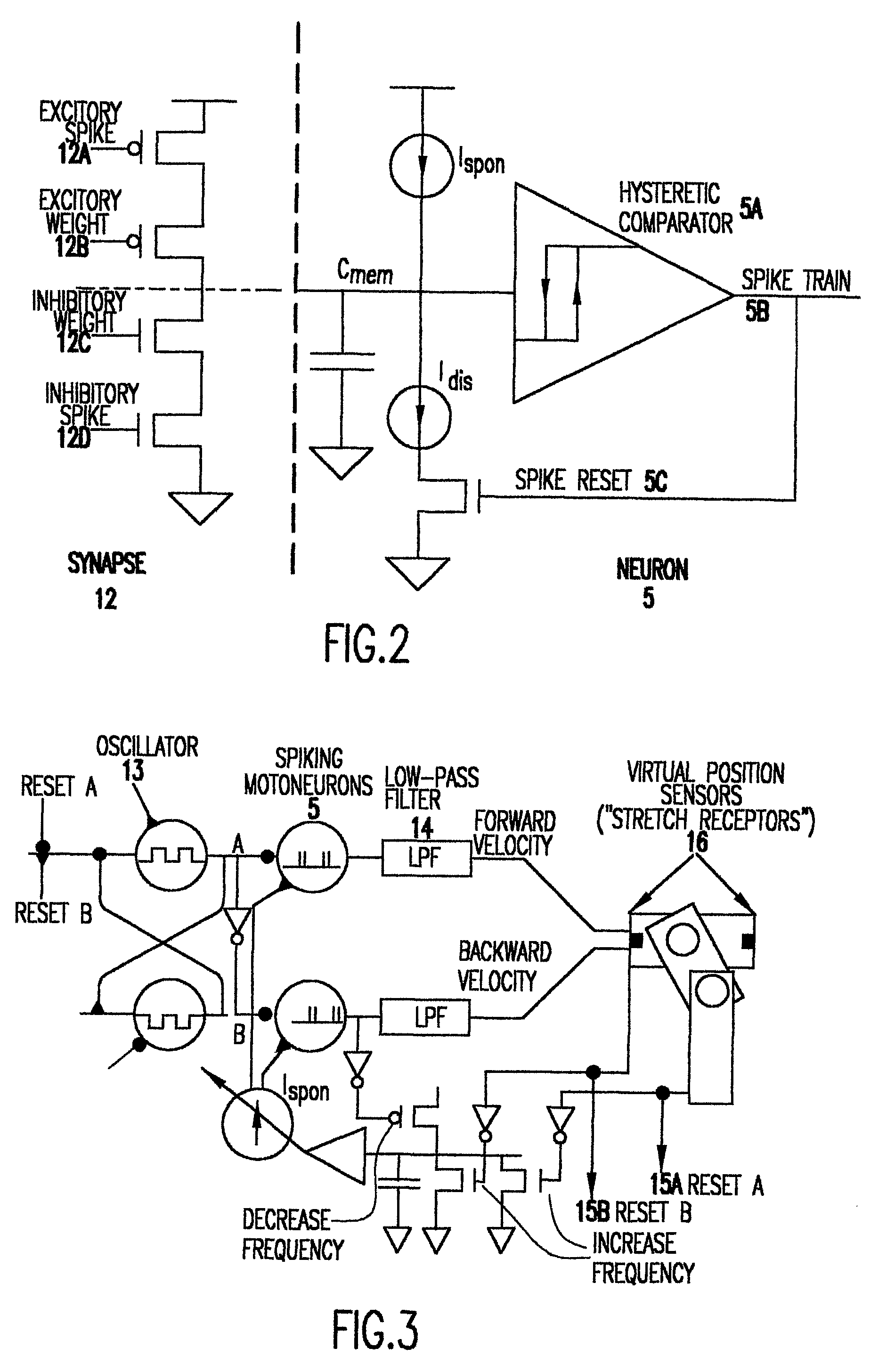
[0087] A robot comprising a biomorphic leg was constructed using a neuromorphic chip on which CPGs were modeled as distributed systems of non-linear oscillators. To provide basic coordination in a leg, two neurons were physically coupled together to achieve oscillations. They were coupled together to be alternatively active, with the alternating activity as the basic coordination that drove the hip of the robot. A phase control circuit governed the phase difference between the neurons. The oscillator neurons drove two integrate-and-fire spiking motoneurons, which drove an actuator. (The spiking neuron could also drive biological muscle or it could also be used to drive a pneumatic cylinder, a McKibben actuator or biomuscle directly).

[0088] The robot used servomotors to provide electrical power. To be compatible with this technology, low-pass filters 14 were applied to the spiking neurons and the resulting smooth graded velocity signal was integrated.

[0089] The circuit...


PUM


Abstract

An artificial Central Pattern Generator (CPG) based on the naturally-occuring central pattern generator locomotor controller for walking, running, swimming, and flying animals may be constructed to be self-adaptive, by providing for the artificial CPG, which may be a chip, to tune its behavior based on sensory feedback. It is believed that this is the first instance of an adaptive CPG chip. Such a sensory feedback-using system with an artificial CPG may be used in mechanical applications such as a running robotic leg, in walking, flying and swimming machines, and in miniature and larger robots, and also in biological systems, such as a surrogate neural system for patients with spinal damage.

Description

RELATED APPLICATION [0001] This is a PCT application claiming priority based on U.S. application 60 / 201,748 filed May 4, 2000, which is incorporated by reference herein.[0002] Statement Regarding Government Funding [0003] This invention was made under NSF grant number 9896362. The Government may have certain rights in this invention.FIELD OF THE INVENTION [0004] The invention generally relates to robotics and movement control, and more particularly, to rhythmic movement control systems that are sensitive and adaptive to the environment in which they are used. BACKGROUND OF THE INVENTION [0005] Basic rhythmic movements in animals are generated by a network of neurons in the spinal cord called the Central Pattern Generator (“CPG”). Walking, running, swimming, and flying animals have a biological locomotor controller system based on a CPG, which is an autonomous neural circuit generating sustained oscillations needed for locomotion. Naturally-occurring CPGs have been studied and are be...

Claims


Application Information

Patent Timeline
Patent Type & Authority Applications(United States)
IPC IPC(8): G06F19/00A61B5/22A61B19/00A61F2/70A61F2/72A61N1/36B25J9/16B62D57/032G06N3/06
CPCA61F2/72A61F2002/704A61N1/36003B25J9/161B62D57/032G06N3/061
Inventor ETIENNE-CUMMINGS, RALPHLEWIS, M. ANTHONY
Owner ETIENNE CUMMINGS RALPH
Learn More