
Hoisting device

a technology of hoisting device and swaying handle, which is applied in the field of hoisting device, can solve the problems of inexpedient movement of the assistant, the drawback of the system, and the assistant's work load, and achieve the effect of reducing the physical load of the assistan

Active Publication Date: 2007-06-14
V GULDMANN AS
View PDF10 Cites 0 Cited by
  • Summary
  • Abstract
  • Description
  • Claims
  • Application Information

AI Technical Summary

Benefits of technology

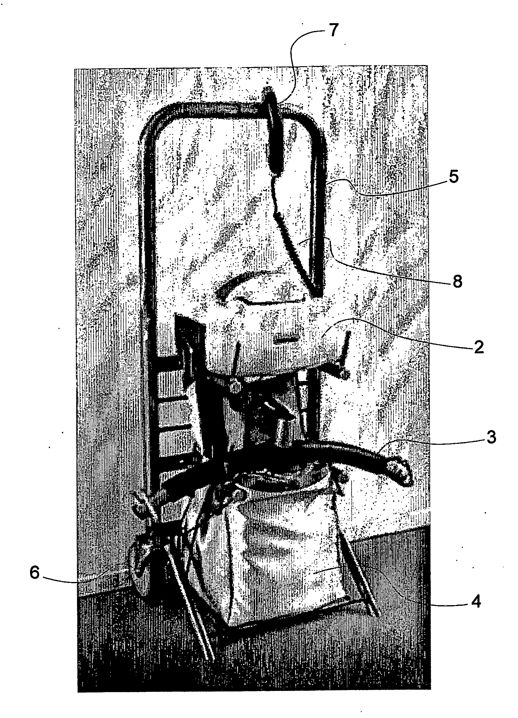
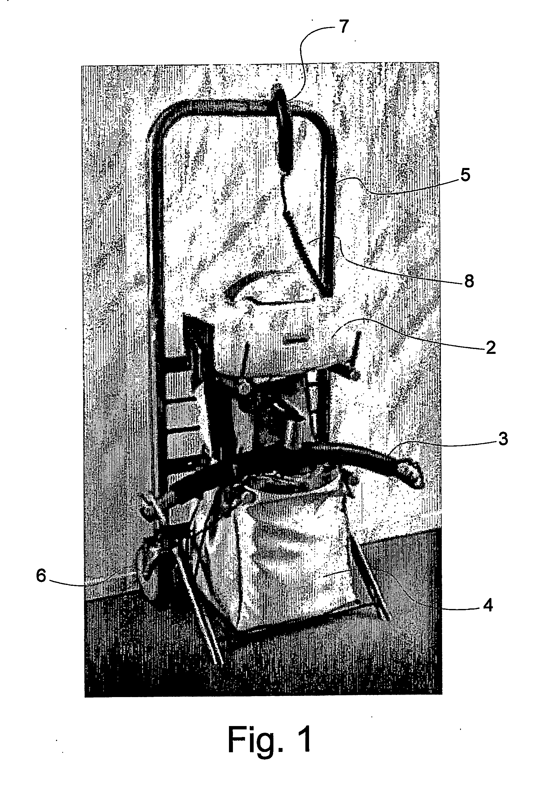
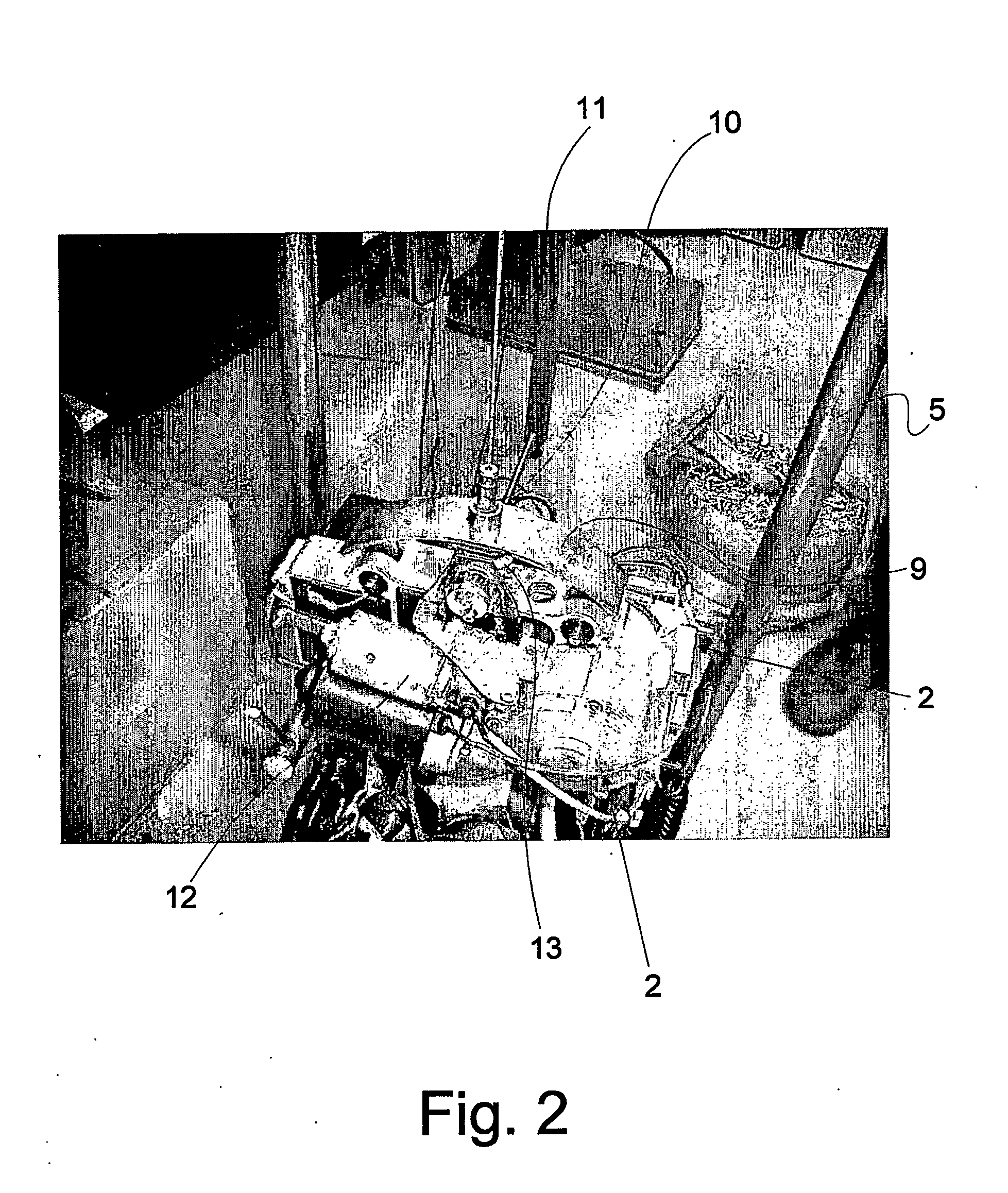
[0028] In a first embodiment of the invention, the means of the winding arrangement are integrated in the hoisting module and includes a reel and a motor unit. These means are built into the hoisting module so that the hosting module does not appear from the outside as something more than a very usual hoisting module for permanent rail mounting. The only difference that may be is that a hoisting module for a movable hoisting device is made with an extra frame in which the first section of the coupling arrangement is coupled, meaning that the lifting height is slightly reduced.
[0056] The support holder with wheels is used when the hoisting module is to be transported from place to place or from room to room, and it is adapted so that besides the hoisting module there is space for a lifting bracket and / or lifting canvas so when the assistant comes with the support holder, he has all the items required for enabling, after suspending the hoisting module and mounting the lifting bracket and the lifting canvas, lifting of the user, and this provides walking several times after the items is avoided.

Problems solved by technology

The drawback of this is that each time the assistant is to suspend the hoisting module in the trolley, some physical work is required, and repeated mounting and dismounting will cause a considerable work load on the assistant.
Furthermore, there is another drawback of this system.
The drawback is that the trolley is disposed in the ceiling-mounted rails which are typically at a level more than 2 m above the floor, meaning that the assistant is to lift hoisting module, typically weighing between 4 and 10 kgs, up from the floor and to an overhead-position for mounting the hoisting module on the trolley at all.
This movement is inexpedient for the assistant since it implies a heavy lift which according to the Labour Environment Act is to be reduced or entirely removed.
The trolleys may have hanging straps which is a disadvantage since the free height is reduced.
The drawback of this is, however, that the lifting bracket, which is disposed directly under the hoisting module, causes that the person sitting in the lifting canvas will either get his view blocked by the hoisting module during the transport or hit his head against the hoisting module as it is situated at a level at which a person sitting in a lifting canvas will have his head.
This is a great disadvantage for a person that cannot control his body movements by himself.
This is a drawback since the assistant is to perform a heavy lift again.

Method used


Image

  • Hoisting device
  • Hoisting device
  • Hoisting device

Examples


first embodiment

[0028] In the invention, the means of the winding arrangement are integrated in the hoisting module and includes a reel and a motor unit. These means are built into the hoisting module so that the hosting module does not appear from the outside as something more than a very usual hoisting module for permanent rail mounting. The only difference that may be is that a hoisting module for a movable hoisting device is made with an extra frame in which the first section of the coupling arrangement is coupled, meaning that the lifting height is slightly reduced.

[0029] In order to operate the winding arrangement separately from the hoisting module, the means of the winding arrangement are made with a reel on which the wire connection is to rolled up and a motor unit connected to the reel so that the wire connection can be rolled up until the first section of the coupling arrangement reaches and engages the second section of the coupling arrangement.

[0030] The first section of the coupling ...

second embodiment

[0033] In the invention, the means of the winding arrangement are integrated in the trolley and include a reel and a motor unit. By placing the means of the winding arrangement in the trolley instead of changing the hoisting module for the existing stationary hoisting devices, one may use a common hoisting module on which is provided a locking bracket which is made with the previously mentioned coupling possibilities for the first section of the coupling arrangement.

[0034] The reel on which the wire connection is provided, will again be of the type that functions according to the roller blind principle, so that one may dispose the end of the wire connection with the first section at an arbitrary level and hold it at an arbitrary level. This, however, requires a release option between reel and motor unit.

[0035] This entails that the wire connection by unrolling can be passed from ceiling and down towards the floor, where the hoisting module is located in a cart / support holder. After...

third embodiment

[0041] In the invention, the means of the rolling up arrangement is a manual winding reel provided with a control means and a trolley provided with a reversing reel.

[0042] In this embodiment, it is manual lifting which is performed. This means that the winding reel e.g. may be a handle in which a spring loaded winding reel provided with control means may automatically roll up the wire connection, and by action of weight on the wire connection may unroll the wire connection, whereby the control means are used for controlling the specific unrolling and rolling up of the wire connection.

[0043] This implies that an assistant is still to lift the full weight of the hoisting module, but the way in which the hoisting module is lifted is more proper ergonomically, so that it is not so hard a load for the assistant to lift the hoisting module in place up under the ceiling. Hereby it is possible to mount the hoisting module manually in the rail, irrespectively how high the rail is mounted.

[...


PUM


Abstract

The present invention concerns a hoisting device including a hoisting module which is replaceably connected with a coupling arrangement for a trolley which is mounted in a ceiling-mounted rail arrangement, where the coupling arrangement is provided in two sections, where the first section is mounted on the hoisting module, and the second section is mounted in connection with the trolley, and where the hoisting module includes a lifting strap arranged for rolling up and unrolling and for fastening a lifting bracket and / or lifting canvas, where the first section of the coupling arrangement is mounted releasably on the hoisting module, that the first section and the second section of the coupling arrangement are mutually connected with a wire connection which is connected with a winding arrangement that includes means dimensioned for lifting the weight of hoisting module, lifting bracket and lifting canvas.

Description

SCOPE OF THE INVENTION [0001] The present invention concerns a hoisting device including a hoisting module which is replaceably connected with a coupling arrangement for a trolley which is mounted in a ceiling-mounted rail arrangement, where the coupling arrangement is provided in two sections, where the first section is mounted on the hoisting module, and the second section is mounted in connection with the trolley, and where the hoisting module includes a lifting strap arranged for rolling up and unrolling and for fastening a lifting bracket and / or lifting canvas. [0002] The invention furthermore concerns methods for using a hoisting device by suspending and taking down a hoisting module. BACKGROUND OF THE INVENTION [0003] In the health sector, e.g. in hospitals, old people's homes or in home care, mechanical aids are used for performing heavy lifting, e.g. lifting of a patient from bed to chair, or a person from a position in a house to another position in the house. [0004] These...

Claims


Application Information

Patent Timeline
Patent Type & Authority Applications(United States)
IPC IPC(8): A61G7/10
CPCA61G7/1015A61G7/1042A61G7/1061A61G2200/34
Inventor BOGH-SORENSEN, OLE
Owner V GULDMANN AS
Learn More