
Combustion chamber distance control for combustion-powered fastener-driving tool

a technology of combustion chamber and distance control, which is applied in the direction of manufacturing tools, stapling tools, nailing tools, etc., can solve the problems of reducing affecting the service life of the piston, so as to reduce the shock-induced damage and ensure the vacuum return of the piston

Active Publication Date: 2007-06-14
ILLINOIS TOOL WORKS INC
View PDF24 Cites 48 Cited by
  • Summary
  • Abstract
  • Description
  • Claims
  • Application Information

AI Technical Summary

Benefits of technology

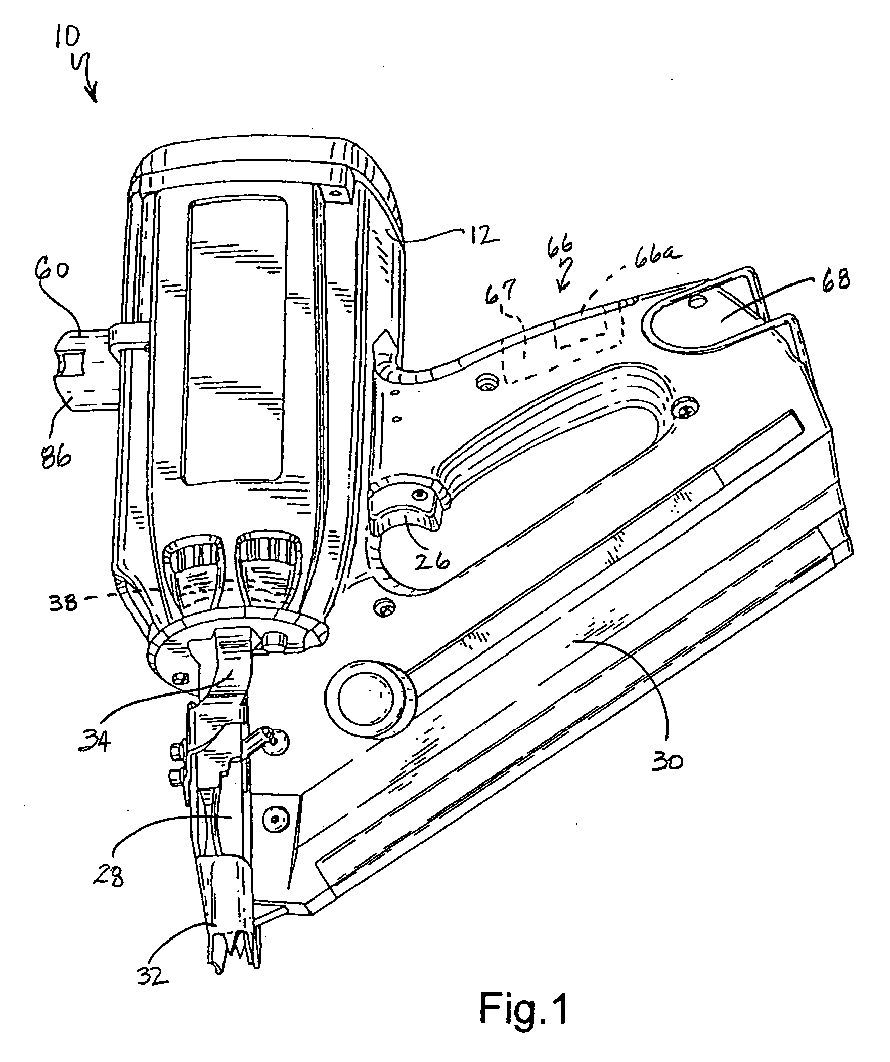
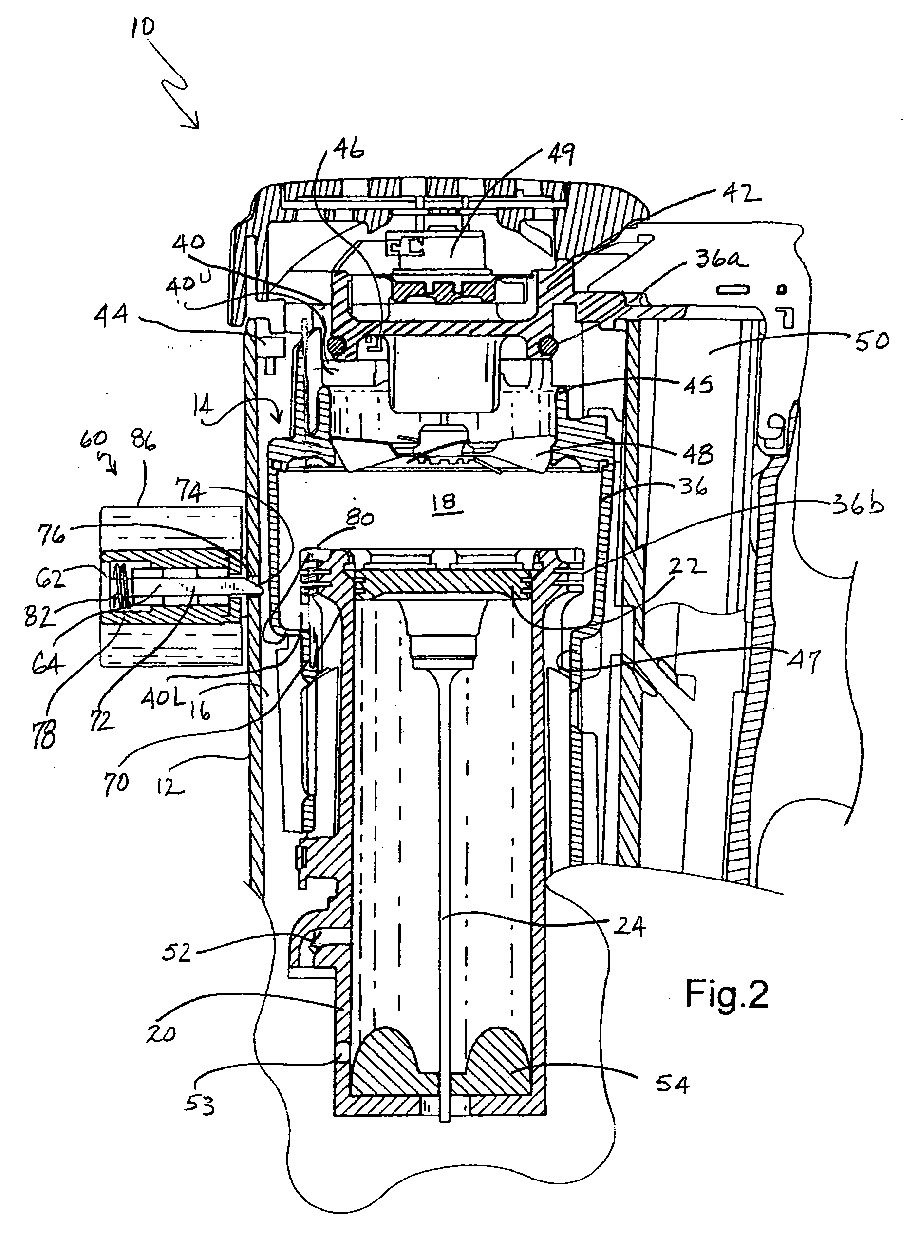
[0015] The above-listed needs are met or exceeded by the present combustion-powered fastener-driving tool which overcomes the limitations of the current technology. Among other things, the present tool incorporates an electromechanical device configured for managing the combustion chamber in a sealed position for a specific time duration, resulting in reliable vacuum return of the piston. To accommodate manufacturing tolerance variations and to reduce shock-induced damage, the lockout device is positioned in the tool to allow for relative movement of the valve sleeve without causing opening of the combustion chamber. The lockout device also accommodates overtravel of the valve sleeve past the point at which the combustion chamber is sealed. Relative distances of valve sleeve overtravel, lockout device location and chamber switch actuation range are all coordinated to allow for the desired tolerances and movement of the valve sleeve while maintaining the combustion chamber in a closed position.
[0016] In the preferred embodiment, the lockout device is an electromagnetic latch connected to the tool and the valve sleeve that holds the valve sleeve in a closed position when the electromagnet is energized. A magnetic plate is moved into contact with the electromagnet by a bracket attached to the valve sleeve. When the electromagnet is energized it attracts the magnet plate, preventing the valve sleeve from retracting. Once the electromagnet is de-energized, the valve sleeve retracts and moves to the open position, drawing the magnetic plate away from the electromagnet. The lockout device provides for overtravel of the valve sleeve while still preventing the valve sleeve from breaking the vacuum seal and opening the combustion chamber.

Problems solved by technology

This causes the vacuum to be lost and piston travel will stop before reaching the top of the cylinder.
It is disadvantageous to maintain the chamber closed longer than the minimum time to return the piston, as cooling and purging of the tool is prevented.
The main deficiency of this approach is that the piston requires the use of a manual reset rod to return the piston to pre-firing if the piston does not fully return due to a nail jam or perhaps a dirty / gummy cylinder wall.
A piston that does not return will cause the chamber to remain closed; therefore the tool cannot be fired again.
Such precision is difficult to maintain when mass producing the tools.
Furthermore, the stressful operational environment of such tools enhances the potential for combustion-induced shock forces to damage the solenoid lockout mechanism.

Method used


Image

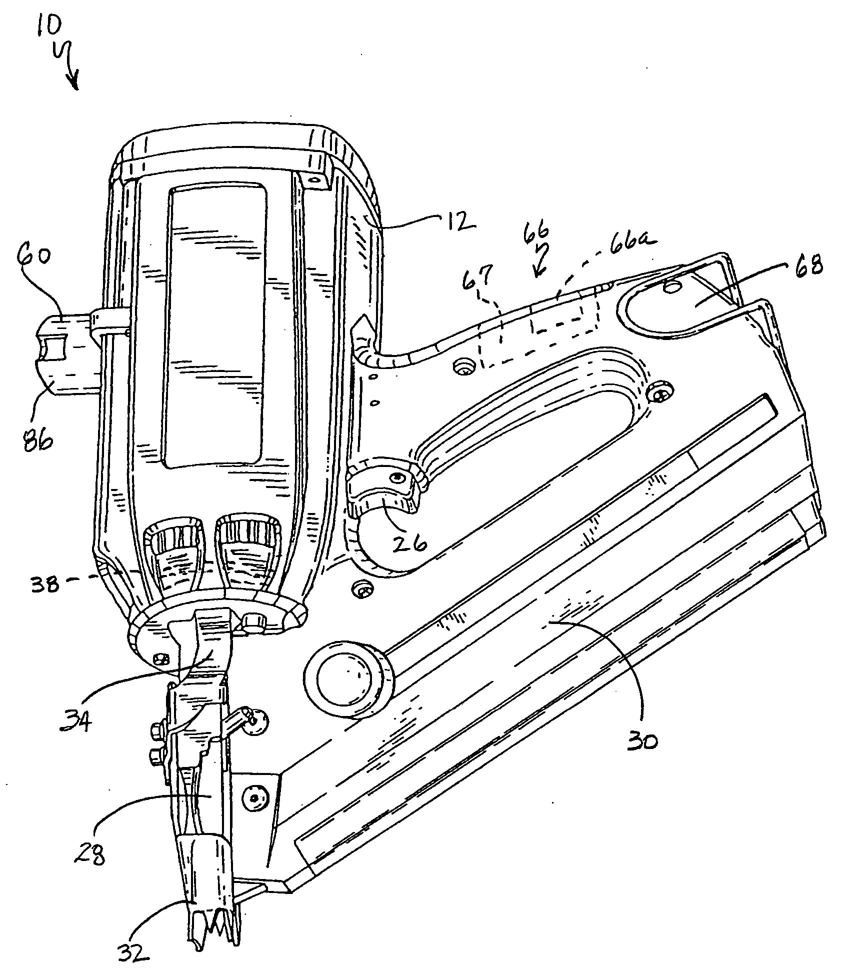
  • Combustion chamber distance control for combustion-powered fastener-driving tool
  • Combustion chamber distance control for combustion-powered fastener-driving tool
  • Combustion chamber distance control for combustion-powered fastener-driving tool

Examples


embodiment 90

[0046] Referring now to FIG. 4, an alternate embodiment to the lockout device 60 is generally designated 90. Shared components with the embodiment of FIGS. 1-3 are designated with identical reference numbers. A main distinction of the embodiment 90 is that the delay of the opening of the valve sleeve 36 during the combustion cycle is obtained through an electromagnetic device 92 mounted to a fixed position on the tool 10, such as the power source 14, and preferably the cylinder head 42, however other locations are contemplated. It will be seen that the electromagnetic device 92 operates along an axis which is parallel to the direction of reciprocation of the piston 22 and the valve sleeve 36. As is the case with the electromagnet 62, the device 92 is connected to the control program 66a. The electromagnetic device 92 depends from the cylinder head 42 so that a contact end 94 is in operational relationship to the valve sleeve 36.

[0047] In the present embodiment, the valve sleeve 36 i...

embodiment 60

[0057] Upon ignition or firing of the spark plug 46, as is known the piston 22 is forced down the cylinder 20. The user then typically lifts the tool 10 to move it to the next fastener position on the workpiece. Due to the permitted overtravel of the valve sleeve 36 relative to the cylinder head 42 as well as the lockout device 110, as the user lifts the tool, the short leg 126 is movable down the alignment shaft 116 and is protected from impact damage by the dampening element 134, which is compressible (FIG. 8). Since the retaining bracket 136 is fixed to the magnetic plate 118, the valve sleeve bracket short leg 126 compresses the dampening element 134 against the retaining bracket and cannot advance beyond this point until the electromagnet device 114 is de-energized by the control program 66a, and releases the magnetic plate. As a result, the valve sleeve 36 is prevented from retracting beyond a sealed position. Once the electromagnet device 114 de-energizes, the movement of the...

embodiment 110

[0058] It will be understood that in the embodiment 110, the pin and sleeve arrangement of the alignment shaft 116 may alternatively be fixed to the magnetic plate 112 instead of the electromagnetic device 114. Also, while only one lockout assembly 90, 100, 110 is illustrated per tool 10, the number and varied positioning of additional assemblies is contemplated depending on the application.


PUM

PropertyMeasurementUnit
Distanceaaaaaaaaaa

Abstract

A combustion-powered fastener-driving tool includes a combustion-powered power source including a cylinder head and a combustion chamber defined by the cylinder head, a valve sleeve and an upper surface of a reciprocating piston, the valve sleeve reciprocable relative to the cylinder head between a rest position and a pre-firing position. The valve sleeve has a range of positions between a first sealing position in which the combustion chamber is closed, and said pre-firing position in which the valve sleeve is prevented from further movement. A lockout device is associated with the power source and has an actuated position configured for preventing the reciprocation of the valve sleeve beyond the first sealed position to open the combustion chamber, but permitting movement of the valve sleeve from the first sealed position to the pre-firing position until the piston returns to a piston pre-firing position post combustion.

Description

RELATED APPLICATION [0001] This application is a Continuation-In-Part of U.S. Ser. No. 11 / 028,432 filed Jan. 3, 2005 entitled: COMBUSTION CHAMBER CONTROL FOR COMBUSTION-POWERED FASTENER-DRIVING TOOL, which claims priority under 35 USC §120 from U.S. Ser. No. 60 / 543,053, filed Feb. 9, 2004.BACKGROUND [0002] The present invention relates generally to fastener-driving tools used to drive fasteners into workpieces, and specifically to combustion-powered fastener-driving tools, also referred to as combustion tools or combustion nailers. The invention is specifically directed towards lockout devices for retaining the combustion chamber of such combustion tools closed pending return of the piston to a prefiring position. [0003] Combustion-powered tools are known in the art. Representative tools are manufactured by Illinois Tool Works, Inc. of Glenview, Ill. for use in driving fasteners into workpieces, and are described in commonly assigned patents to Nikolich U.S. Pat. Re. No. 32,452, and...

Claims


Application Information

Patent Timeline
IPC IPC(8): B25C1/14B25C1/08
CPCB25C1/08
Inventor MOELLER, LARRY M.ZHAO, HANXIN
Owner ILLINOIS TOOL WORKS INC
Learn More