Dynamic aperture for display systems

a display system and dynamic aperture technology, applied in the field of dynamic aperture for display systems, can solve the problems of reducing the overall system brightness, increasing the bit depth, and losing light during the entire time of reduced illumination, so as to improve the image quality of the display system, increase the cost advantage of slm display systems, and reduce design time and costs.

Inactive Publication Date: 2007-06-14
TEXAS INSTR INC
View PDF4 Cites 13 Cited by
  • Summary
  • Abstract
  • Description
  • Claims
  • Application Information

AI Technical Summary

Benefits of technology

[0008] These and other problems are generally solved or circumvented, and technical advantages are generally achieved, by preferred embodiments of the present invention which provides a system and apparatus for improving image quality in display systems.
[0012] An advantage of a preferred embodiment of the present invention is that standard off-the-shelf motors and feedback systems can be used. This can lead to an easy-to-implement way to increase the display system's bit-depth, potentially improving the image quality of the display system without requiring a significant investment in development time and money. This can further increase a cost advantage of SLM display systems over other display technologies.
[0013] A further advantage of a preferred embodiment of the present invention is that the use of standard parts enables practically all display system designers to integrate the present invention into their display systems. Furthermore, the use of time tested parts can reduce design time and costs.

Problems solved by technology

This can result in an increased bit-depth.
One disadvantage of the prior art is that the use of the NDF causes loss of light during the entire time of reduced illumination.
The loss of light results in a reduction of overall system brightness.
A second disadvantage of the prior art is that the variable apertures have made use of motors similar to those used in hard disk drives.
These motors can be hard to use and may require design expertise not readily available to all display system implementers.
This can result in increased display system design and production costs, potentially negating some of the cost benefits of using SLM technology.

Method used


Image

  • Dynamic aperture for display systems
  • Dynamic aperture for display systems
  • Dynamic aperture for display systems

Examples


Embodiment Construction

[0022] The making and using of the presently preferred embodiments are discussed in detail below. It should be appreciated, however, that the present invention provides many applicable inventive concepts that can be embodied in a wide variety of specific contexts. The specific embodiments discussed are merely illustrative of specific ways to make and use the invention, and do not limit the scope of the invention.

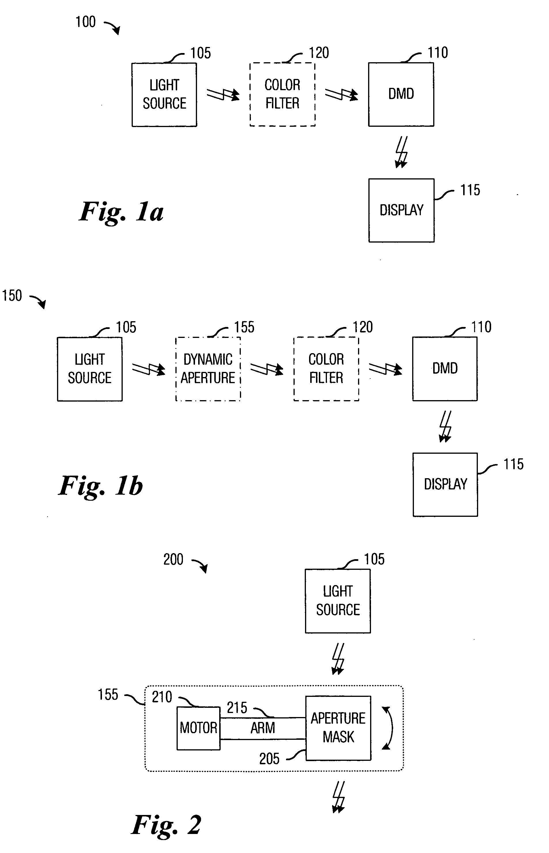
[0023] The present invention will be described with respect to preferred embodiments in a specific context, namely a SLM display system making use of digital micromirror devices (DMD). The SLM display system may make use of light created from three component (primary) colors, red, green, and blue. The invention may also be applied, however, to other SLM display systems such as those using light modulators with technologies such as liquid crystal, deformable micromirrors, liquid crystal on silicon (LCOS), micro electro-mechanical systems (MEMS), and so forth. Furthermore, th...


PUM


Abstract

System and apparatus for improving the display quality of display systems. A preferred embodiment comprises a planar object configured to variably pass light produced by a light source located on a first side of the planar object to a second side of the planar object, and a motor coupled to the planar object, the motor to rotate the planar object and change the amount of light passed by the planar object. The planar object includes a semi-circular beveled portion formed on a first side of the planar object. A slot with monotonically increasing width is cut along a spine of the semi-circular beveled portion and through the planar object and depending upon a width of the slot that is in front of the light source, the planar object passes a different amount of light. The motor is a DC brushless motor or a limited angular torque motor.

Description

TECHNICAL FIELD [0001] The present invention relates generally to a system and an apparatus for displaying images, and more particularly to a system and an apparatus for improving the display quality of display systems. BACKGROUND [0002] Display systems for use in displaying still images and moving images that make use of a spatial light modulator (SLM) use a bright light that either reflects off or shines through the SLM to project images onto a display screen. These display systems have enabled large high-quality displays that are relatively inexpensive, compact for the display size, and reliable. [0003] One important factor in determining image quality is the display system's bit-depth, defined as a ratio of the display system's brightest white to its darkest black. The greater the bit-depth, the smoother the displayed image appears on the display screen. A display system with a low bit-depth will have visible banding in the images that it displays, especially in portions of the ...

Claims


Application Information

Patent Timeline
Patent Type & Authority Applications(United States)
IPC IPC(8): B60Q1/14
CPCG03B33/06G03B33/08H04N9/3155H04N9/3197G03B21/2053
Inventor SMITH, STEVEN EDWARDMARSHALL, STEPHEN WESLEY
Owner TEXAS INSTR INC
Why Eureka
Try Eureka