Image forming apparatus and method of controlling the same

a technology forming apparatus, which is applied in the direction of electrographic process apparatus, instruments, optics, etc., can solve the problems of increasing the running cost preventing degradation of unable to satisfactorily improve the image forming capability of image forming apparatus, so as to curb the rise in running cost and improve image formation capability

Inactive Publication Date: 2007-06-14
CANON KK
View PDF3 Cites 20 Cited by
  • Summary
  • Abstract
  • Description
  • Claims
  • Application Information

AI Technical Summary

Benefits of technology

[0017] It is an object of the present invention to provide an image forming apparatus and a method of controlling the apparatus that can improve image formation capability to a satisfactory degree while curbing the rise in running cost.
[0022] With the above arrangement, adjustment images are formed on the image support member. The adjustment images having different densities so as to carry out image adjustment are read by the reading device. The optical reflectivity of the image support member is higher than that of patches. An output from the reading device is read with the number of readings set to a large value or with the time interval between readings set to a small value when the densities of the adjustment images are susceptible to the optical reflectivity of the image support member. Also, the output from the reading device is read with the number of readings set to a small value or with the time interval between readings set to a large value when the densities of the adjustment images are less susceptible to the optical reflectivity of the image support member. Thus, the number of readings or the time interval between readings can be suitably controlled to improve image formation capability to a satisfactory degree while curbing the rise in running cost.

Problems solved by technology

This causes an increase in the running cost of the image forming apparatuses.
It is therefore impossible to prevent degradation in the image formation capability of an image forming apparatus.
It is therefore impossible to satisfactorily improve the image formation capability of an image forming apparatus.
Also, to increase the number of times a shadow area is read, the shadow area has to be long, resulting in increased toner consumption.

Method used


Image

  • Image forming apparatus and method of controlling the same
  • Image forming apparatus and method of controlling the same
  • Image forming apparatus and method of controlling the same

Examples


Embodiment Construction

[0038] The present invention will now be described in detail with reference to the accompanying drawings showing a preferred embodiment thereof.

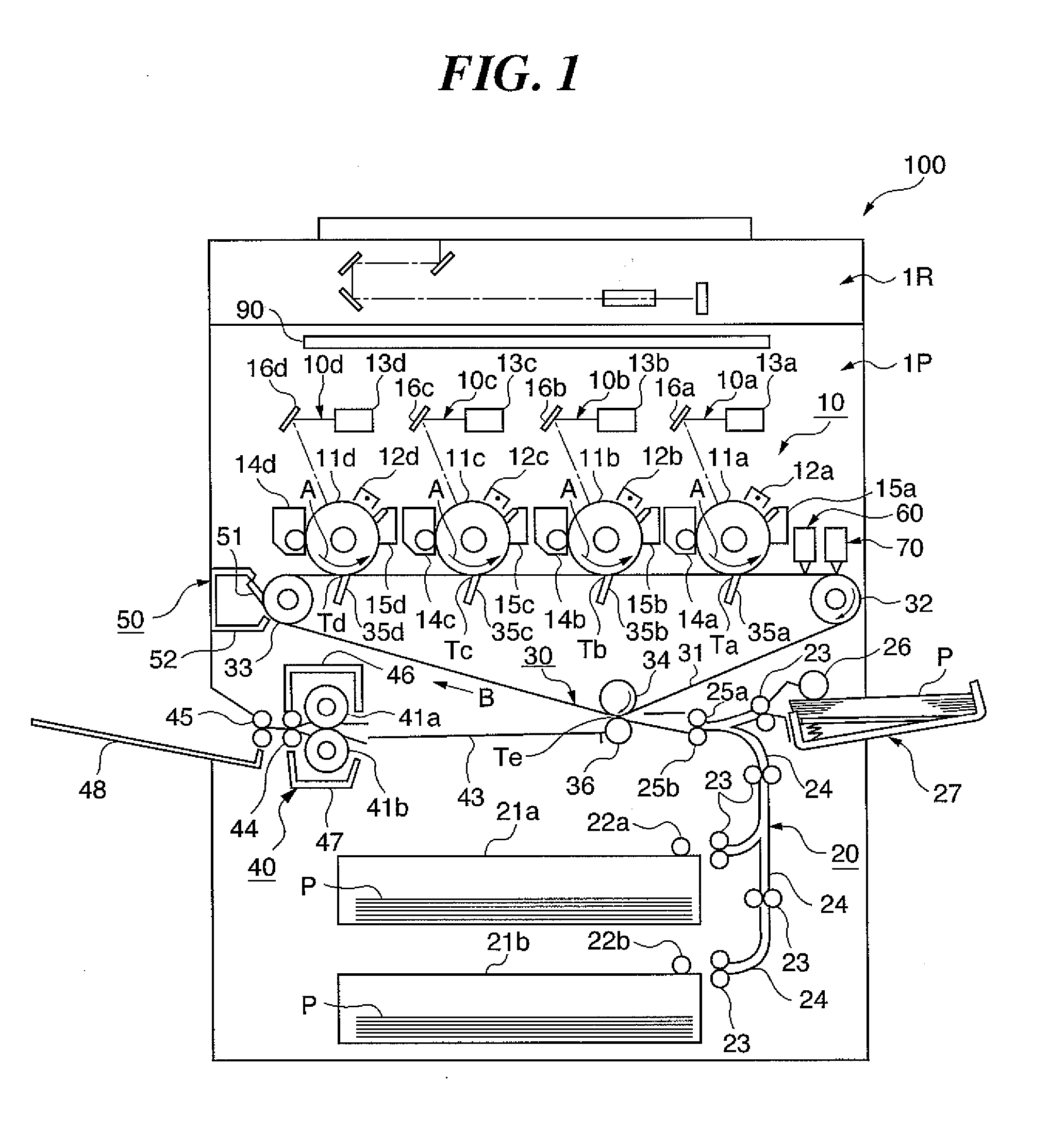
[0039]FIG. 1 is a longitudinal sectional view schematically showing the construction of an image forming apparatus according to an embodiment of the present invention.

[0040] An electrophotographic color copying machine 100 is comprised of an image reading section 1R that reads images on originals as image signals, and an image output section 1P that forms images on an intermediate transfer member based on image signals received from the image reading section 1R.

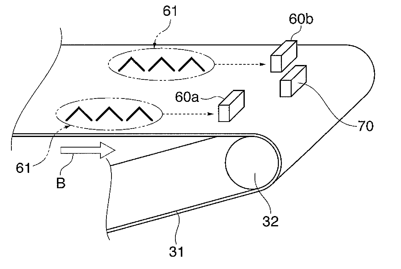
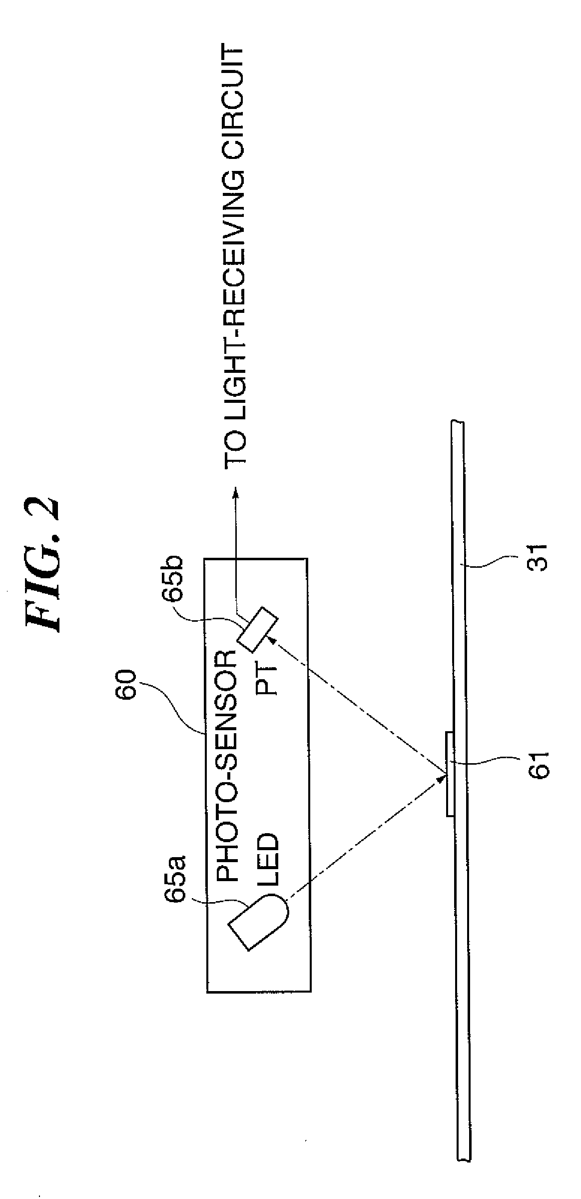
[0041] As shown in FIG. 1, the image output section 1P is comprised of an image forming section 10, a sheet feed unit 20, an intermediate transfer unit 30, a fixing unit 40, a cleaning unit 50, photo-sensors 60 (60a and 60b) in FIG. 2, a density sensor 70 in FIG. 4A, and a control unit 90 in FIG. 7.

[0042] A detailed description will now be given of the units.

[0043] The image form...


PUM


Abstract

An image forming apparatus which can improve image formation capability to a satisfactory degree while curbing the rise in running cost. An image forming device forms adjustment images having different densities on an image support member having a higher optical reflectivity than an optical reflectivity of the adjustment images. A reading reads the adjustment images. An output from the reading device is read at a predetermined number of readings or time interval between readings based on the densities of the adjustment images susceptible to the optical reflectivity of the image support member.

Description

BACKGROUND OF THE INVENTION [0001] 1. Field of the Invention [0002] The present invention relates to an image forming apparatus and a method of controlling the same, and more particularly to an image forming apparatus that forms images on image support members and a method of controlling the same. [0003] 2. Description of the Related Art [0004] Electrophotographic image forming apparatuses are equipped with four image forming stations that carry out electrophotographic processes to form color images, such as black, cyan, magenta, and yellow images, respectively. Each of the image forming stations forms an electrostatic latent image on a photosensitive drum as an image support member by radiating a laser beam from a laser or light from a light-emitting device such as an LED onto the photosensitive drum. The electrostatic latent image formed on the photosensitive drum is then developed by toner supplied from a developing device, so that a visible image (toner image) is formed on the p...

Claims


Application Information

Patent Timeline
Patent Type & Authority Applications(United States)
IPC IPC(8): G03G15/00
CPCG03G2215/00059G03G2215/00063G03G2215/00067G03G15/0194G03G15/0131G03G15/5058G03G2215/0119
Inventor SOYA, TAKASHINOGUCHI, JUNICHIKANNO, TAKASHITAKATA, SHINICHIHAMANO, SHIGEMICHIOKAMOTO, KIYOSHIYAMAZAKI, KATSUYUKIOHTA, TOMOICHIRO
Owner CANON KK
Why Eureka
Try Eureka