

Photovoltaic power generator
a photovoltaic power generator and photovoltaic technology, applied in the direction of light radiation electric generators, instruments, process and machine control, etc., can solve the problems of difficult exploration and specifying a real maximum power point, and achieve the effect of rapid exploration
- Summary
- Abstract
- Description
- Claims
- Application Information
AI Technical Summary
Benefits of technology
Problems solved by technology
Method used
Image

Examples
first embodiment
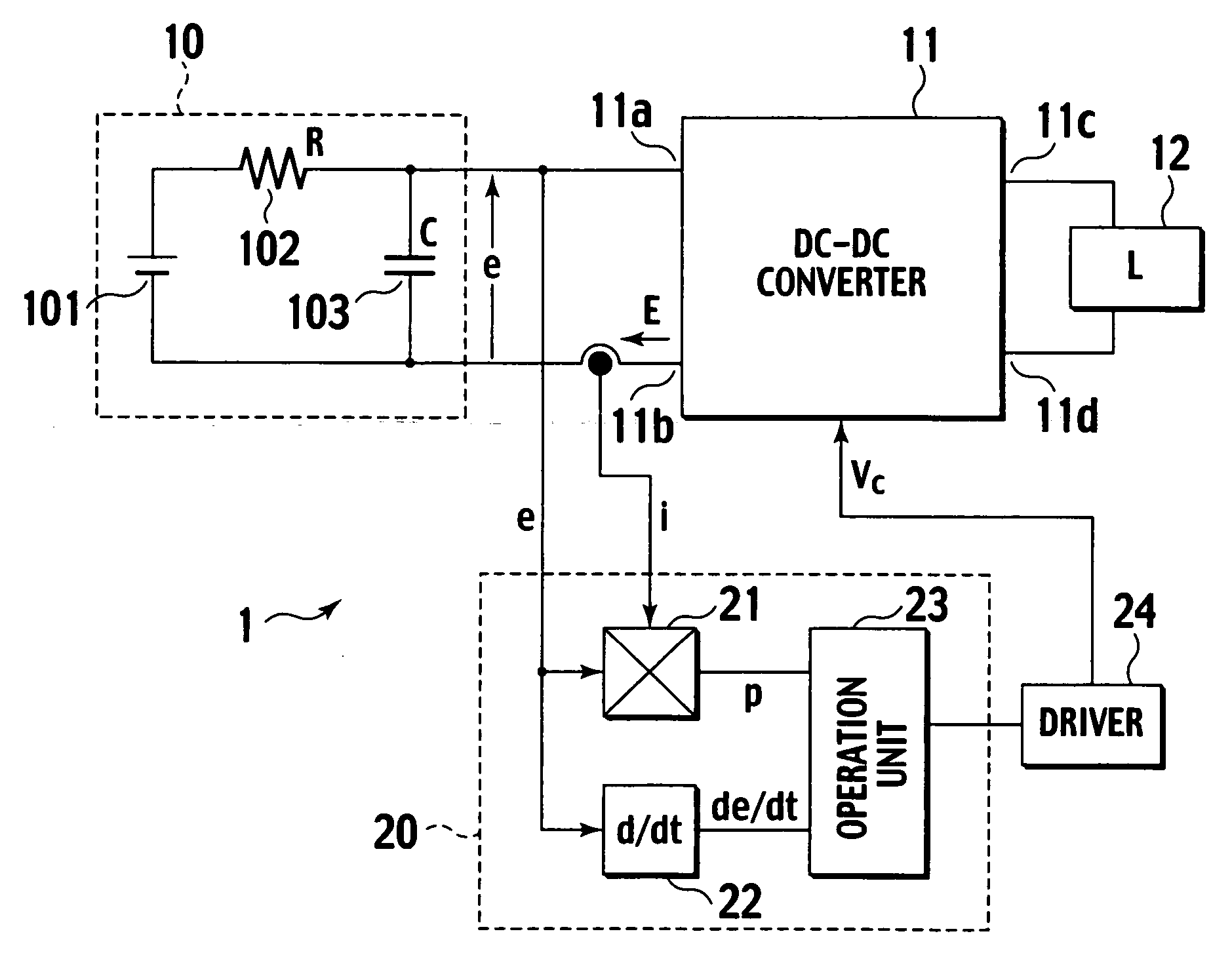
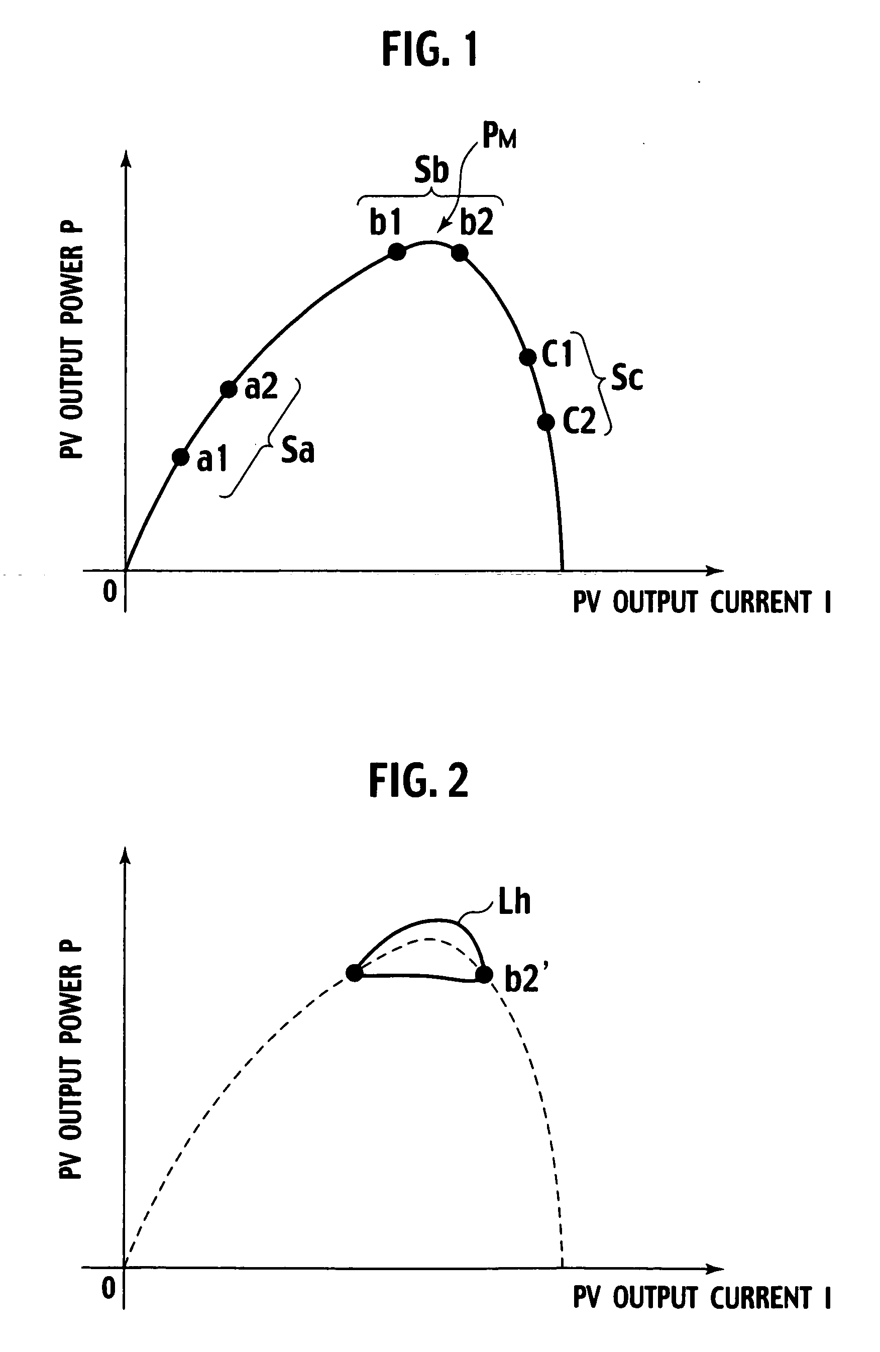
[0029]FIG. 7 shows a configuration of a photovoltaic power generator 1 according to the present invention. Generated power of a solar battery panel 10 is outputted to a load L through the DC-DC converter 11. A controller 20 detects output power p(t) and time differentiation value de(t) / dt of the output voltage based on the output voltage e(t) and the output current i(t) of the solar battery panel 10. The operation unit 20 detects a time point at which the de(t) / dt becomes substantially zero, and calculates output power p(t) at that time point. When sweep / perturbation voltage for exploring one operating point Vop is to be superimposed, the value of de(t) / dt becomes substantially zero at two points. As the time points are defined as t1 and t2 respectively (t12), the operation unit 20 calculates the power variation Pdif from p (t1) and p(t2). At that time, in a case of (i) Pdif>0, the DC-DC converter 11 is controlled such that Vop is increased, and in a case of (ii) Pdif11 is feedback ...
second embodiment
[0037]FIG. 9 shows a more detailed configuration of a controller of a photovoltaic power generator according to a second embodiment of the present invention. The second embodiment is different from the first embodiment only in the operation unit, other configuration thereof is the same as that of the first embodiment, and redundant explanation will be omitted. The second embodiment is different from the first embodiment in that while the photovoltaic power generator of the first embodiment obtains the power variation Pdif by the difference calculation in FIG. 7, the photovoltaic power generator of the second embodiment obtains the power variation Pdif using differential calculation.
[0038] In the second embodiment, time differentiation dp / dt of output power P of a solar battery panel is used for calculating the power variation Pdif. The power differentiation value dp / dt is definite integrated from the time point t1 to time point t2 wherein the voltage differentiation value substanti...
third embodiment
[0044]FIG. 11 shows a photovoltaic power generator of a third embodiment in which the configurations of the present invention shown in FIGS. 7 and 9 are realized. Like the second embodiment, the power variation Pdif is obtained using differentiation calculation.
[0045] According to the photovoltaic power generator of the present embodiment shown in FIG. 11, output voltage e of the solar battery panel 10 is detected by a voltage amplifier 38. Output current i of the solar battery panel 10 is detected by a detection resistor Ri, and is amplified by a transconductance amplifier 21a. The output voltage e is converted into current corresponding to the voltage e by a current source 21b, and is supplied as a bias of the transconductance amplifier 21a. As a result, the current i is multiplied by the voltage e, and a power value p is outputted from a buffer 21c. The power value p is time differentiated by a differentiator 31 and is inputted to the synchronous rectifier 32. On the other hand,...
PUM
 Abstract
Description
Claims
Application Information