
Pneumatic tire

a technology of pneumatic tires and tires, which is applied in the field of pneumatic tires, can solve the problems of reducing the durability of tires and the solution proposed by miyazono would not be appreciated by those in the art for such tires

Inactive Publication Date: 2007-06-21
THE GOODYEAR TIRE & RUBBER CO
View PDF7 Cites 1 Cited by
  • Summary
  • Abstract
  • Description
  • Claims
  • Application Information

AI Technical Summary

Benefits of technology

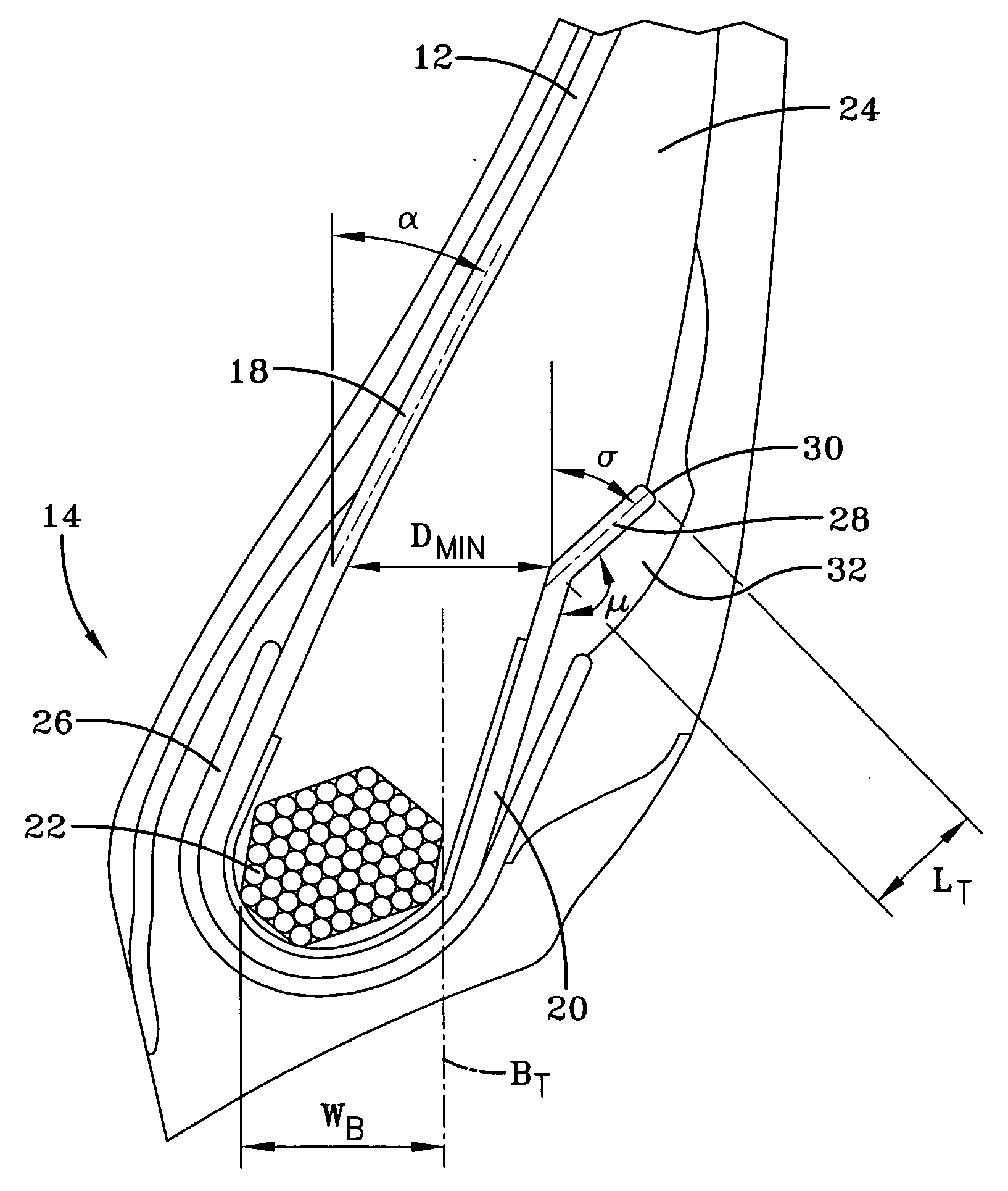
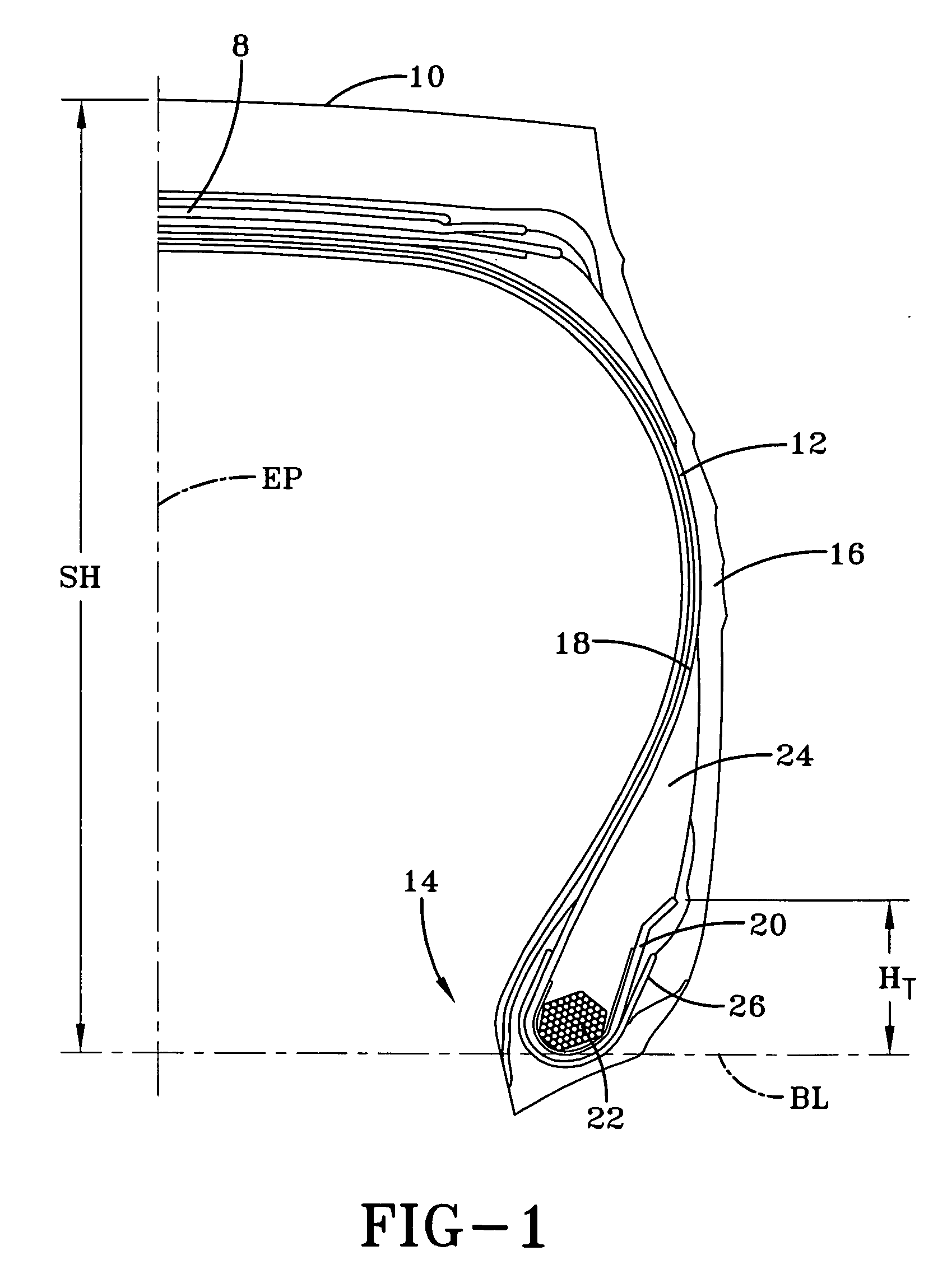
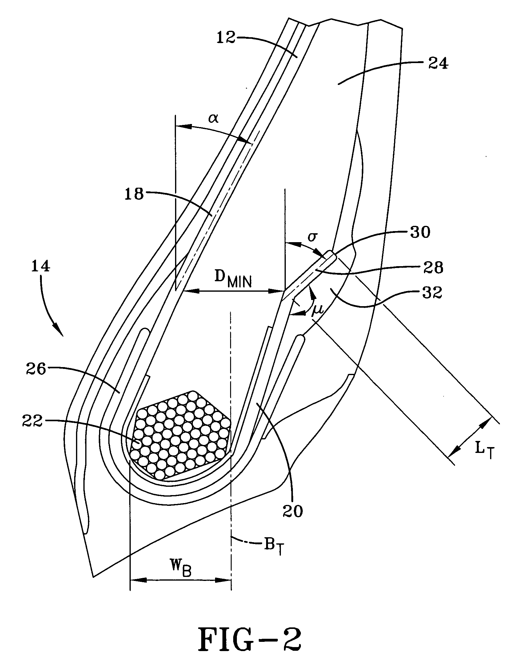
[0007] The present invention is directed to a tire having improved bead durability. Disclosed is a pneumatic radial tire having at least one carcass reinforcing ply and a pair of opposing bead portions. Each bead portion has a bead core and a bead apex, while the carcass reinforcing ply has a main portion and two turnups, with one turnup extending from each end of the main portion and having a terminal end. In each bead portion, there is a minimum distance DMIN between the carcass main portion and the carcass turnup, as measured perpendicular to the tire equatorial plane EP. The distance DMIN is not less than 50% of the maximum bead core width WB as measured perpendicular to the equatorial plane EP. Additionally, in each bead portion, radially outward of the minimum distance DMIN, a radially outermost portion of the carcass turnup extends at an angle so the radially outermost portion of the carcass turnup is divergent from the carcass main portion.

Problems solved by technology

The movement of the carcass ply and the surrounding rubber may result in cracking of the rubber in the tire bead portion, decreasing durability of the tire.
This solution only works when the chafer plies terminate radially above the carcass ply, and provides no solution for a chafer-less tire or a tire wherein the chafer plies terminate radially inward of the carcass ply turnup.
The solution proposed by Miyazono would not be appreciated by those in the art for such tires as the carcass plies and the cord reinforced chafer plies act differently under tension and deflection.

Method used


Image

  • Pneumatic tire
  • Pneumatic tire
  • Pneumatic tire

Examples


Embodiment Construction

[0021] The following language is of the best presently contemplated mode or modes of carrying out the invention. This description is made for the purpose of illustrating the general principles of the invention and should not be taken in a limiting sense. The scope of the invention is best determined by reference to the appended claims. The reference numerals as depicted in the drawings are the same as those referred to in the specification. For purposes of this application, the various embodiments illustrated in the figures each use the same reference numeral for similar components. The structures employ basically the same components with variations in location or quantity thereby giving rise to the alternative constructions in which the inventive concept can be practiced.

[0022] A pneumatic tire in accordance with the present invention is illustrated in FIGS. 1 and 2. The pneumatic tire has a carcass, a belt structure 8 radially outward of the carcass, and a tread 10 radially outwa...


PUM


Abstract

A pneumatic radial tire has at least one carcass reinforcing ply and a pair of opposing bead portions. Each bead portion has a bead core and a bead apex, while the carcass reinforcing ply has a main portion and two turnups, with one turnup extending from each end of the main portion and having a terminal end. In each bead portion, there is a minimum distance DMIN between the carcass main portion and the carcass turnup, as measured perpendicular to the tire equatorial plane EP. The distance DMIN is not less than 50% of the maximum bead core width WB as measured perpendicular to the equatorial plane EP. In each bead portion, radially outward of the minimum distance DMIN, a radially outermost portion of the carcass turnup extends at an angle so the radially outermost portion of the carcass turnup is divergent from the carcass main portion.

Description

[0001] This application claims the benefit of, and incorporates by reference, U.S. Provisional Application No. 60 / 752,416 filed Dec. 21, 2005.FIELD OF THE INVENTION [0002] The present invention is directed to a pneumatic tire. More specifically, the present invention is directed to a pneumatic radial tire wherein the bead portion of the tire is designed for improved durability due to the configuration of the turn-up portion of the carcass reinforcing ply. BACKGROUND OF THE INVENTION [0003] Bead area durability is one of the concerns of the tire industry. A conventional tire bead portion 100 is illustrated in FIG. 7. What is conventionally considered the main portion 104 of a carcass reinforcing ply extends radially inward toward the tire rim and is turned about an inextensible bead core 106 to form a carcass ply turnup 108. The carcass ply turn up 108 extends at a single angle μ relative to a radial line tangent to the axially outermost point of the bead core 106 and parallel to the...

Claims


Application Information

Patent Timeline
IPC IPC(8): B60C15/00B60C9/00
CPCB60C9/04Y10T152/10819B60C15/06B60C9/08
Inventor DU, MINGLIANGNEAL, CHRISTOPHER VINCENT SR.BOROWCZAK, MARCFLEISCHMAN, THOMAS SHERWOODBO, ZHONGHEAKSHANTALA, NAGENDRA PRASAD VENKATALICHT, LAURENTFELLER, JEAN-MARIEBODEUX, JEAN-BERNARDWINKIN, DIDIERVILCHEZ MACURI, FELIX MAXIMO
Owner THE GOODYEAR TIRE & RUBBER CO
Learn More