Chromatography columns and their operation

Active Publication Date: 2007-06-21
SARTORIUS STEDIM CHROMATOGRAPHY SYST LTD
View PDF16 Cites 18 Cited by
  • Summary
  • Abstract
  • Description
  • Claims
  • Application Information

AI Technical Summary

Benefits of technology

[0032] By operating the drive from one end, in practice preferably the base of the column which may be a base mounted on a stand, we can provide the advantages of the invention without relying on overhead structures or separate units. Nevertheless, the skilled person will appreciate that the advantageous exposure of the piston at the opposite end of the column tube may be achieved by other means if extra drives or attachments to other structures are tolerated, e.g. to dri

Problems solved by technology

The alignment and lifting structures cause significant obstructions around the tube, and need to be carefully laid out to provide sufficient clearance at some part of the circumference for insertion/removal of the permeable retaining elements if this is to be an operational requirement.
The illustrated column has a 1400 mm diameter and would be very difficult to manoeuvre without a powered lift.
The desc

Method used


Image

  • Chromatography columns and their operation
  • Chromatography columns and their operation
  • Chromatography columns and their operation

Examples


Embodiment Construction

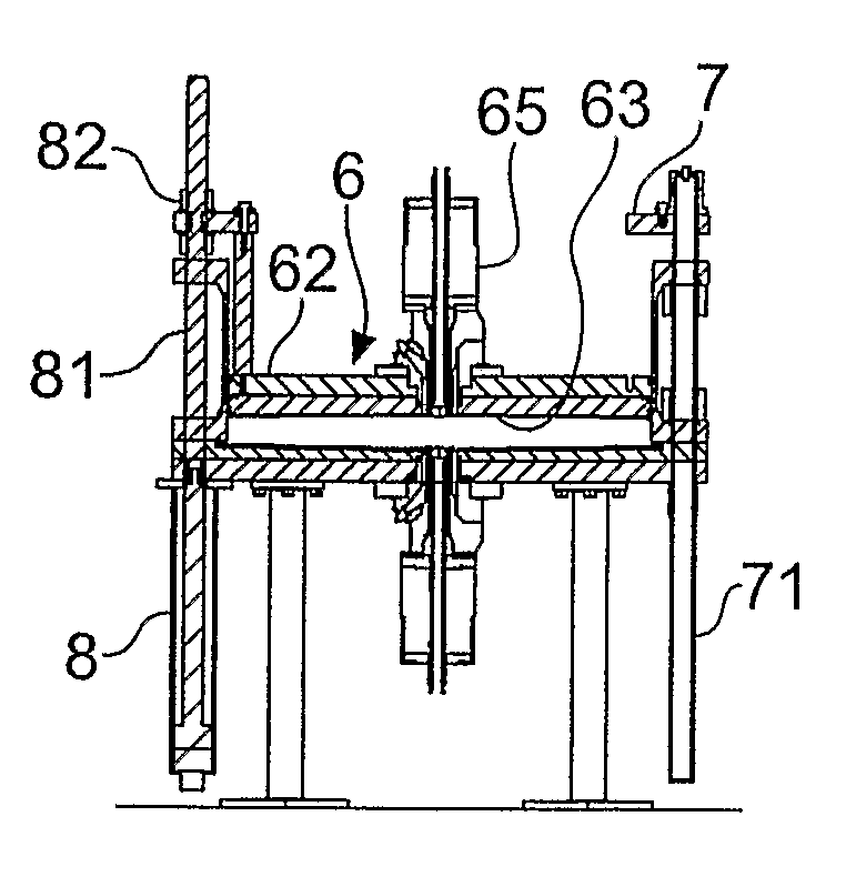
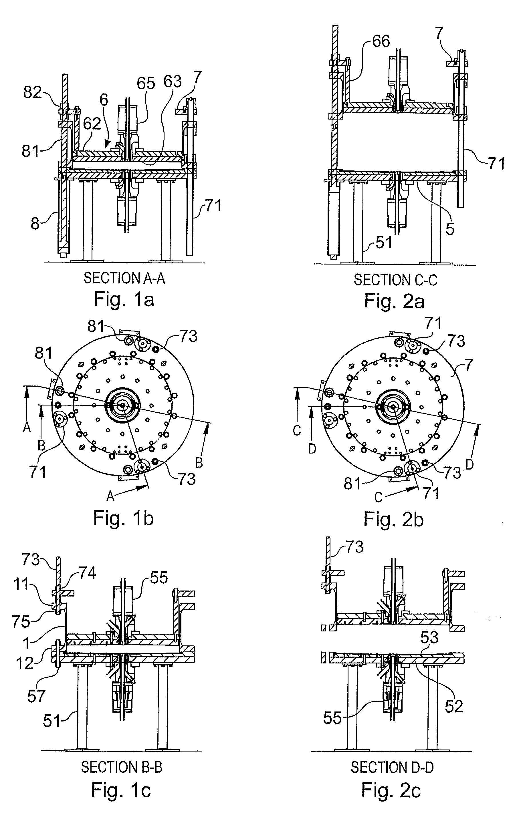
[0055] The column components are broadly similar to those in FIGS. 1 to 5 discussed previously. Thus, the cylindrical stainless steel column tube 101 has upper and lower integral flanges 111, 112, and the base 105 consists of a steel backing plate 152 and a contoured cell plate 153 which carries the bed support mesh. Releasable threaded studs 157 hold the bottom column flange 112 down onto the base, clamping a fixed seal 159 described later. The column base 105 stands on support legs 151, here a wheeled mobile support, providing a component space beneath the base.

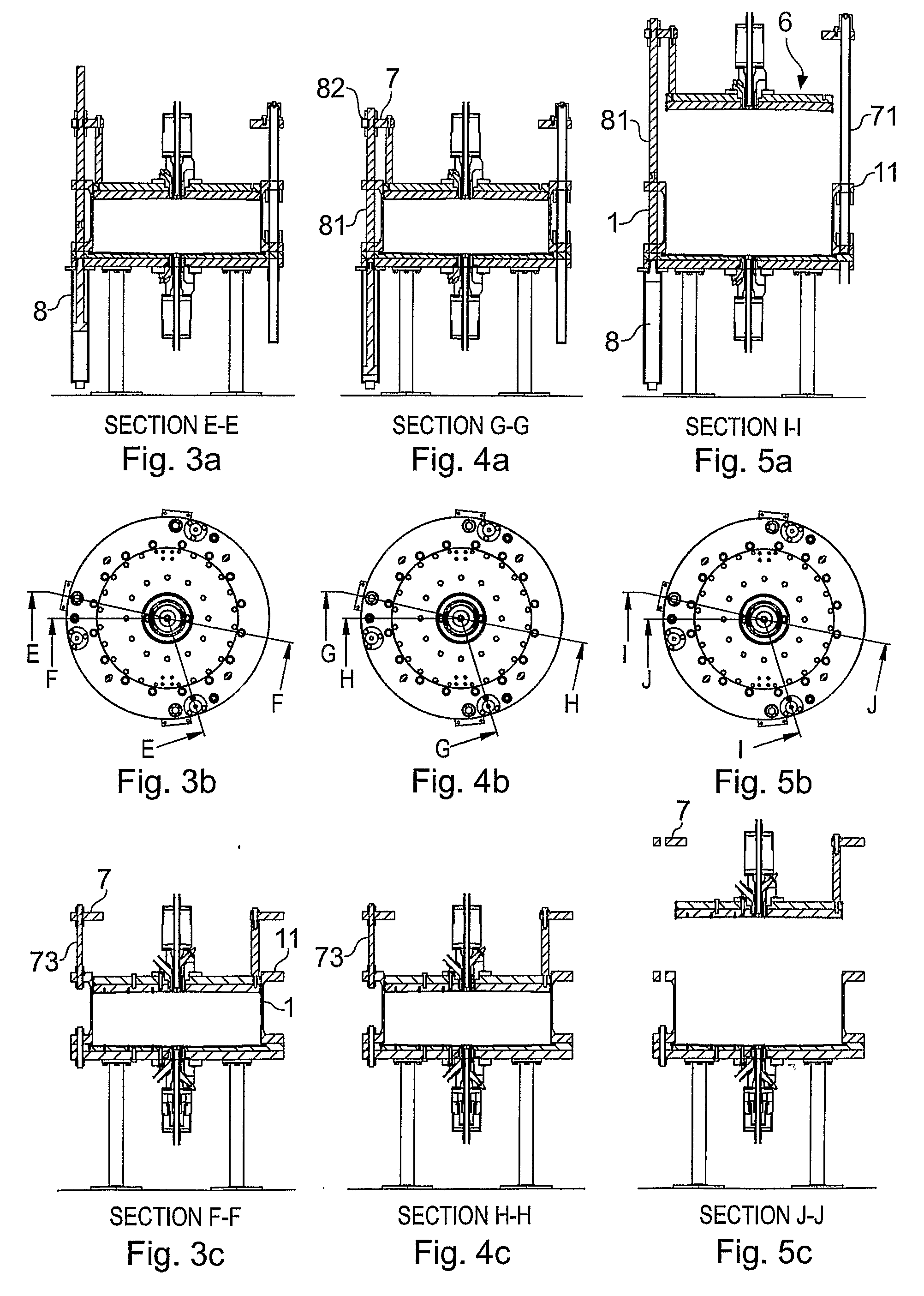
[0056] Continuing with reference to FIGS. 6 to 9, three hydraulic drive cylinders 108 are mounted to the underside of the base plate 152, and each operates a drive rod 181 extending up slidably through an opening in the base 105, a corresponding opening in the lower tube flange 112 and up to the upper flange 111. The upper flange 111 has corresponding holes, and a drive extension rod 183 has its bottom end passing through ...


PUM


Abstract

A method of operating chromatography column apparatus comprising a column tube (101) and first and second discrete end cell structures, associated with the respective ends of the column tube and positionable to close off the column tube and define therein a column space for retaining chromatography medium in use of the apparatus. The first end cell portion comprises a piston portion (106) fitting slidably in the column tube. The column tube and the second end cell structure are separated to provide an access spacing between them. The piston portion (106) of the first end cell structure is advanced through the column tube to expose it at the open second end of the column tube, for maintenance of the piston portion thus exposed. Corresponding chromatography apparatus is another aspect of the disclosure.

Description

FIELD OF THE INVENTION [0001] This invention has to do with chromatography apparatus and methods. It is particularly concerned with systems and methods for gaining access to components of the column e.g. for maintenance, notably the column end cell structures. BACKGROUND OF THE INVENTION [0002] The present discussion relates to apparatus and methods useful in industrial-scale chromatography, e.g. large-scale preparative purification of fine chemicals and pharmaceuticals, including biological products. It is not concerned with laboratory-scale apparatus. Conventionally an industrial-scale chromatography column has a cylindrical axially-vertical column tube with top and bottom end cells, each of which provides a strong backing plate with a fluid inlet / outlet and support for a layer of mesh, sinter or other fluid-permeable retaining material which lets process liquid flow into and out of the chromatography space while retaining the bed of particulate chromatography medium. To provide a...

Claims


Application Information

Patent Timeline
IPC IPC(8): B01D15/08B01D15/22G01N30/52G01N30/60
CPCG01N30/6021G01N30/603G01N30/6047G01N2030/522B01D15/22
Inventor SPENCER, JAMES
Owner SARTORIUS STEDIM CHROMATOGRAPHY SYST LTD
Why Eureka
Try Eureka