Method and device for calculating motion vector between two images and program of calculating motion vector between two images

Inactive Publication Date: 2007-06-21
FUJIFILM CORP
View PDF4 Cites 14 Cited by
  • Summary
  • Abstract
  • Description
  • Claims
  • Application Information

AI Technical Summary

Benefits of technology

[0046] According to the above configuration, comparison images are cut out from plural second images obtained by shifting pixels and compared with the reference image to thereby obtain

Problems solved by technology

Therefore, an operation load is large and time required for the operation is also long.
As a result, the calculating of the motion vector may not be completed until a next frame is displayed.
Thu

Method used


Image

  • Method and device for calculating motion vector between two images and program of calculating motion vector between two images
  • Method and device for calculating motion vector between two images and program of calculating motion vector between two images
  • Method and device for calculating motion vector between two images and program of calculating motion vector between two images

Examples


first embodiment

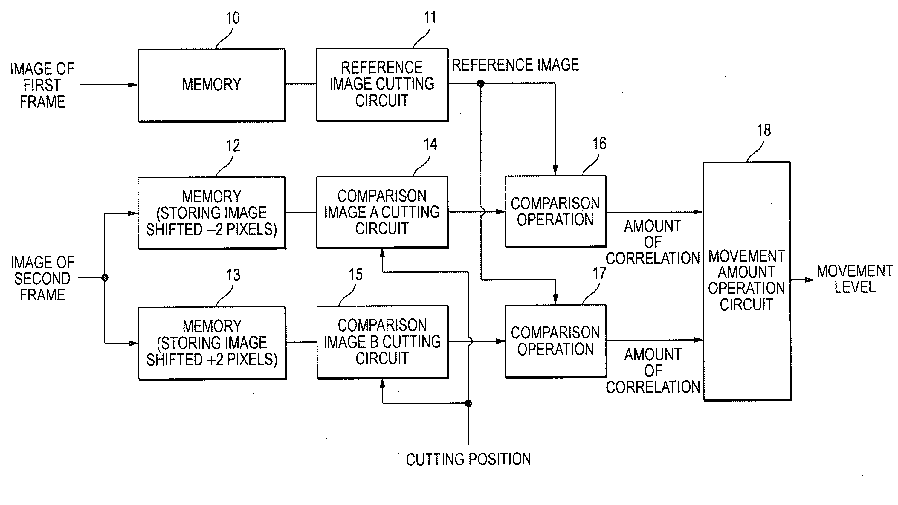
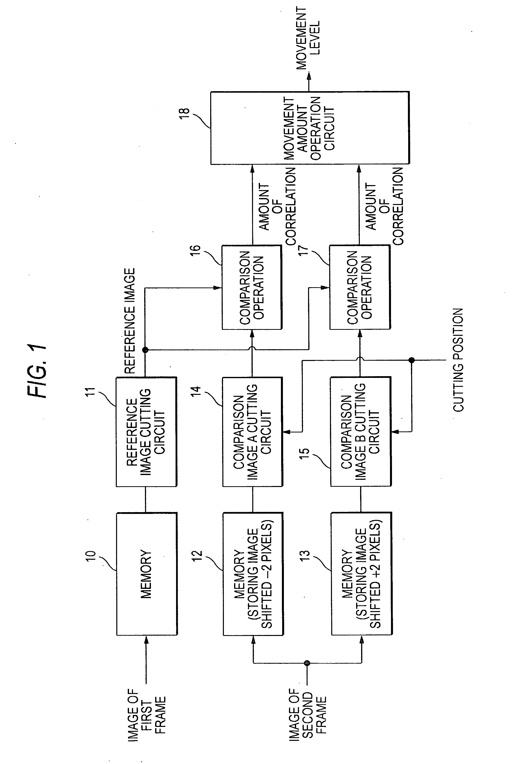
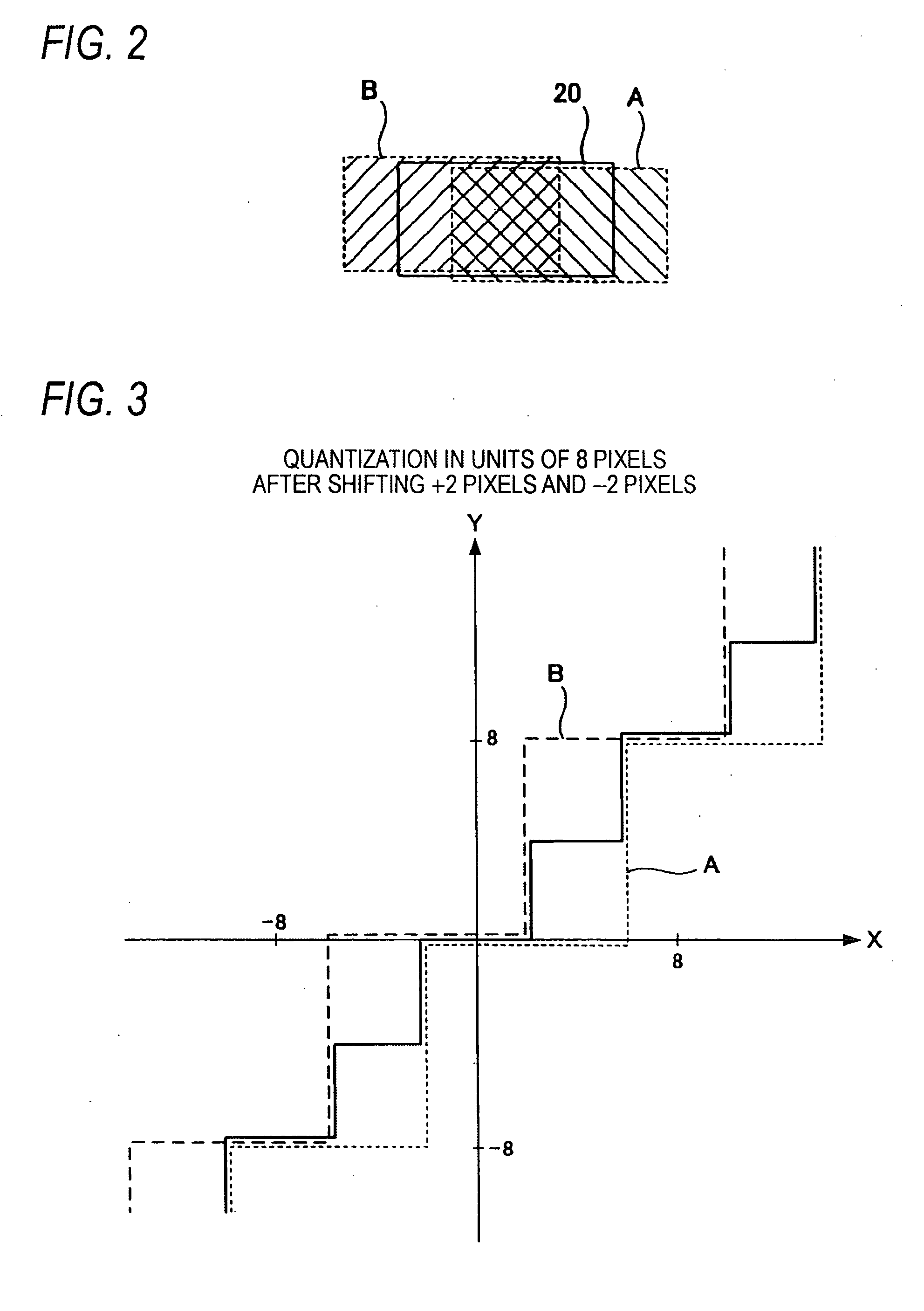
[0068]FIG. 1 is a view illustrating the configuration of an apparatus for calculating a motion vector between two images according to the first embodiment of the invention. A shift unit of a block from which a comparison image is cut out is n-th power of 2 (n is desired number). For the purpose of clear explanation, it is assumed that the shift unit is eight pixels in the following description.

[0069] Referring to FIG. 1, a motion vector calculating apparatus according to the first embodiment includes a memory 10 that receives and stores an image of a first frame, a reference image cutting circuit 11 that cuts out a reference image located at a predetermined address from the data stored in the memory 10, a memory 12 that receives an image of a second frame to be compared with the first frame and stores the image of the second frame with shifting the image of the second frame −2 pixels, and a memory 13 that receives the image of the second frame and stores the image of the second fra...

second embodiment

[0078]FIG. 4 is a view illustrating the configuration of an apparatus for calculating a motion vector between two images according to a second embodiment of the invention. Prior to describing the second embodiment shown in FIG. 4, a principle of calculating a motion vector according to the second embodiment will be explained with reference to FIGS. 5 to 8.

[0079] In the first embodiment, a big block is set on the first frame and the comparison operation between the reference image within the set block and the comparison image within a block of the second from is performed to obtain the motion vector. However, in the case where a part of an image within a block moves significantly, for example, if a motion picture in which an animal runs has been captured, camera shake of the entire image and movement of the animal captured in a part of the image cannot be distinguished. Accordingly, since the movement of the animal may increase a calculation error of a camera shake motion vector of ...

third embodiment

[0113]FIG. 10 is a flow chart illustrating a processing sequence of a program of calculating a motion vector between two images according to a third embodiment of the invention. Video data, which is stored in a recording medium after capturing of motion pictures with a digital camera or the like, is input to a personal computer or the like. The program of calculating a motion vector between two images is then executed by an operation processing unit of the computer. Thus, video data from which camera shake is eliminated is created.

[0114] The program of calculating a motion vector between two images according to the third embodiment causes a computer to execute the same process as that in the first embodiment described above. Specifically, the program of calculating a motion vector between two images according to the third embodiment acquires first image data from the video data, which has transferred from the recording medium to a hard (step S1). Then, the program acquires second i...


PUM


Abstract

A reference image is cut out from a first image and a comparison image is cut out from a second image while shifting a cutting block by n pixels and correlation between each of the comparison images. The reference image is calculated to obtain a motion vector of the second image with respect to the first image. Plural second images (hereinafter, referred to as 2-1 image, 2-2 image, . . . ) obtained by shifting the second image by m pixels (m<n) are created and stored in a memory. Also, when cutting out the comparison image, plural comparison images are cut out from each of the 2-1 image, 2-2 image, . . . and operations of calculating correlation between each of the comparison images and the reference image are performed in parallel.

Description

BACKGROUND OF THE INVENTION [0001] 1. Technical Field [0002] The invention relates to a method and device for calculating a motion vector between two images in order to detect a motion vector (amount of movement and direction of movement) and a program of calculating a motion vector between two images. [0003] 2. Description of the Related Art [0004] In the case of shooting motion pictures while holding, for example, a video camera or a digital still camera having a video recording function with a hand, if the hand holding the camera jiggles, the position of an image of a still object included in an image of a certain frame will move in an image of the next frame, which prevents the image from being clearly distinguished. For this reason, a motion vector of an image of the next frame with respect to an image of the certain frame is detected so as to compensate for the camera shape so that images are not blurred. [0005]FIGS. 12A and 12B are views explaining a principle of detecting a ...

Claims


Application Information

Patent Timeline
IPC IPC(8): G06K9/00
CPCG06T7/202G06T7/231
Inventor IWABUCHI, HIROSHIWADA, TETSU
Owner FUJIFILM CORP
Why Eureka
Try Eureka