Conditioning device for liquid handling system liquids

a technology for liquid handling and conditioning devices, applied in chemical methods analysis, material testing goods, water/sludge/sewage treatment, etc., can solve problems such as unpopular use of pressurized gas cylinders

a technology for liquid handling and conditioning devices, applied in chemical methods analysis, material testing goods, water/sludge/sewage treatment, etc., can solve problems such as unpopular use of pressurized gas cylinders

US20070140916A1Inactive Publication Date: 2007-06-21TECAN TRADING AG

Image

  • Conditioning device for liquid handling system liquids
  • Conditioning device for liquid handling system liquids
  • Conditioning device for liquid handling system liquids

Examples


Embodiment Construction

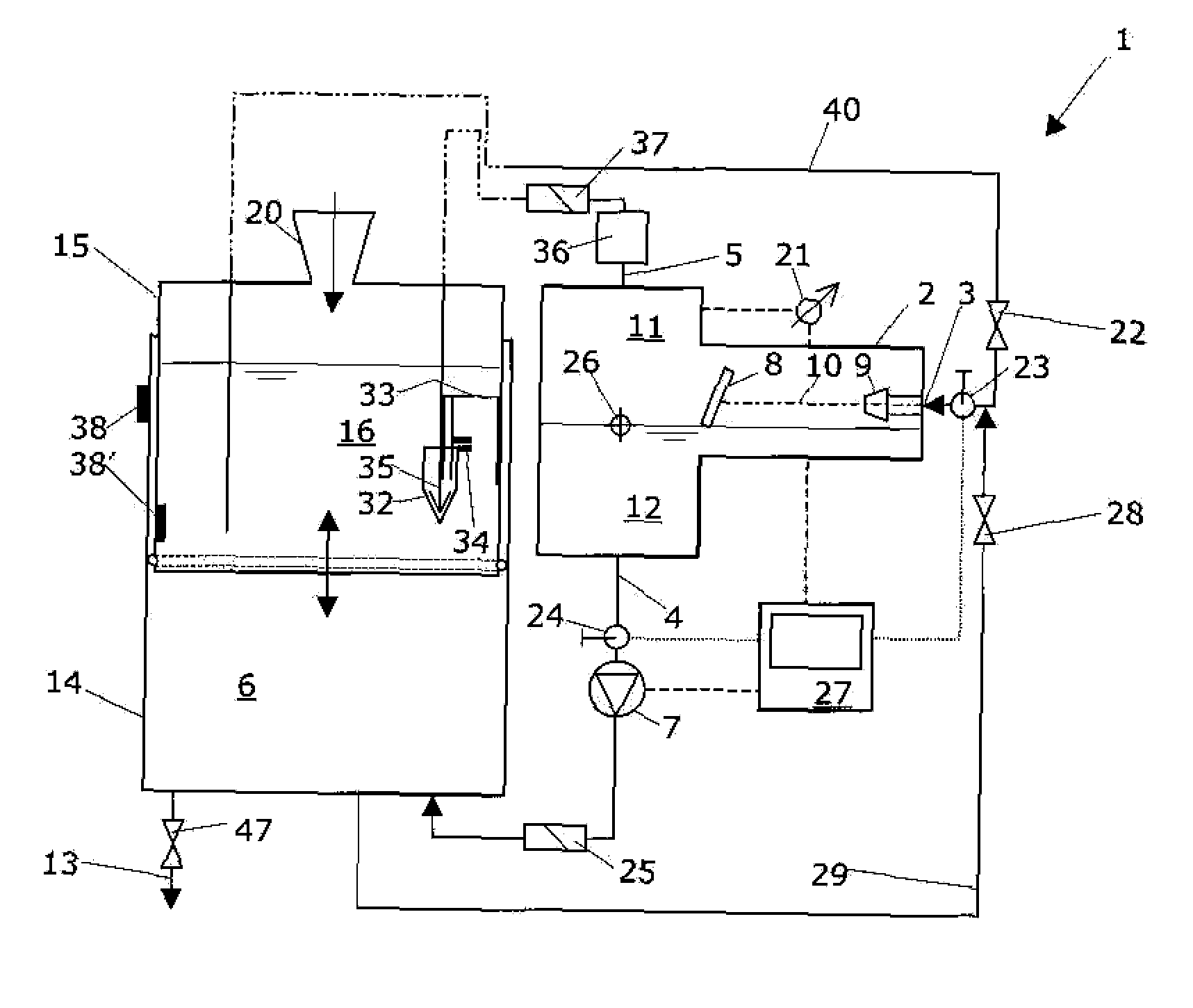
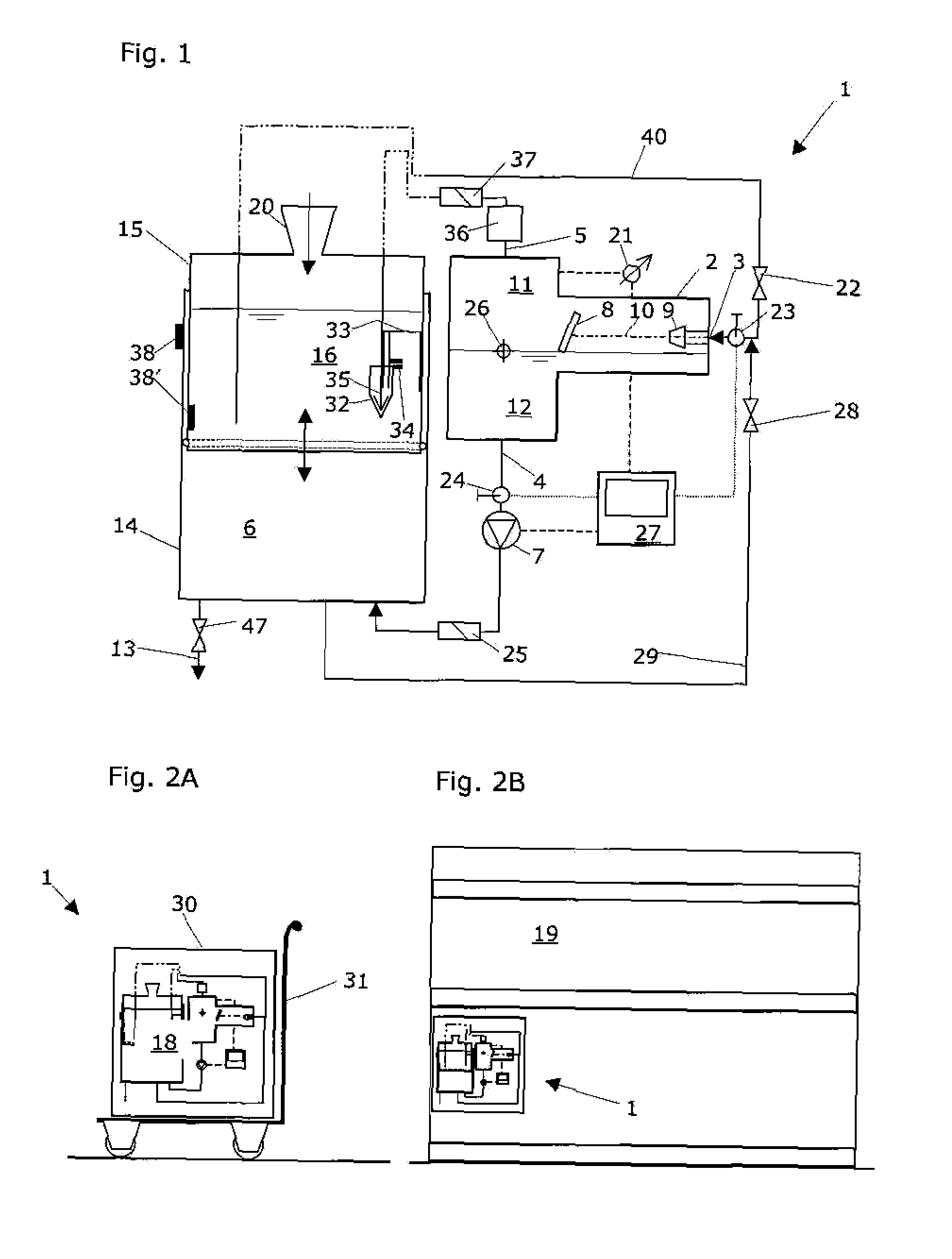
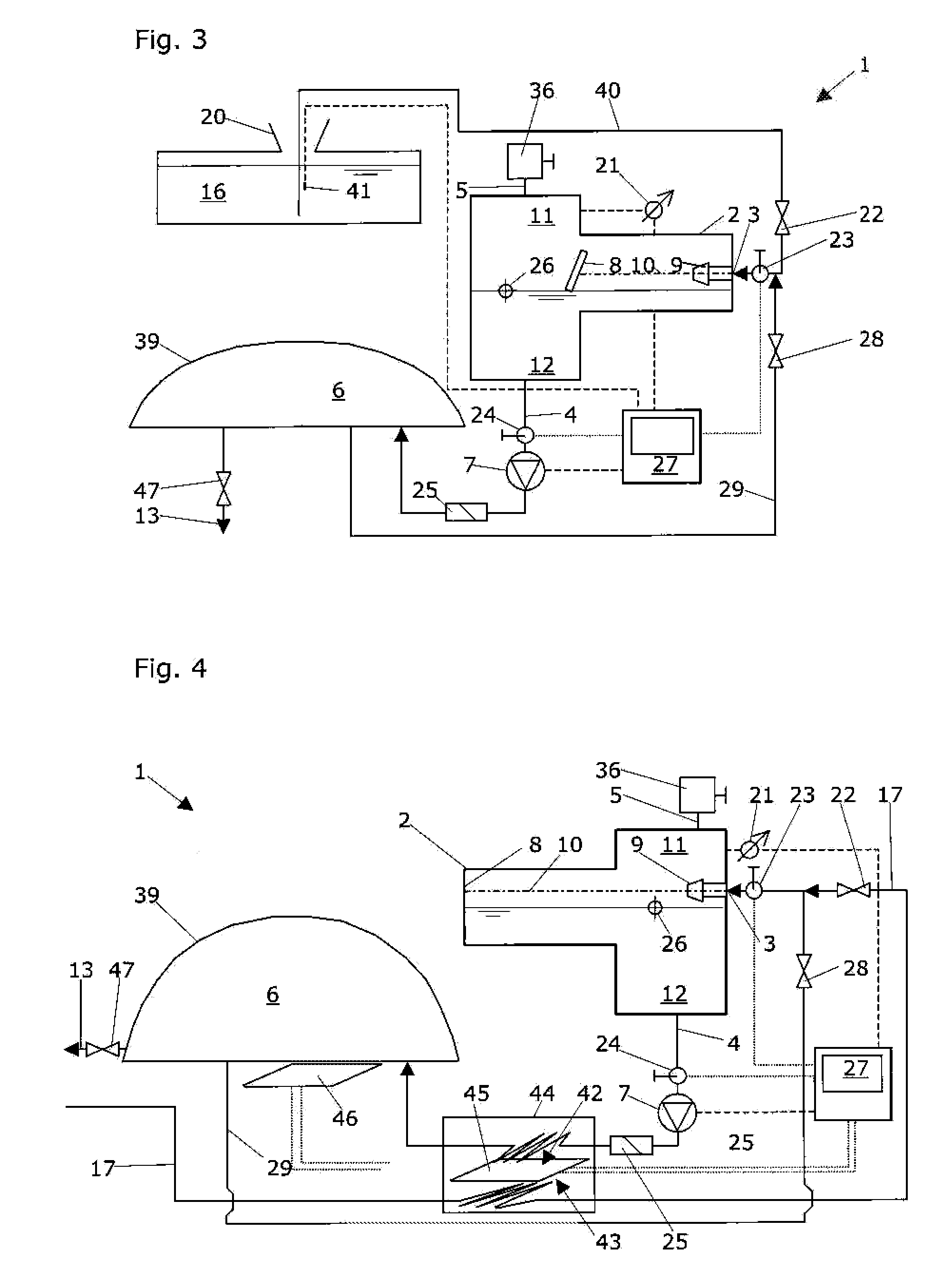
[0026]FIG. 1 shows a vertical partial section through a device according to the present invention according to a first embodiment. This device 1 for conditioning a system liquid for a liquid handling apparatus comprises a degassing chamber 2 for degassing the system liquid. The degassing chamber 2 itself comprises a system liquid injection point 3, a system liquid drain line 4, and a gas drain line 5. In addition, the device 1 comprises a collection chamber 6 for degassed system liquid. This collection chamber 6 is spatially separated from the degassing chamber 2 and connected via a recirculation pump 7 to the system liquid drain line 4 of the degassing chamber 2. The system liquid to be degassed enters the degassing chamber 2 at the injection point 3 via an injection nozzle 9. The device comprises a splash wall 8 in its degassing chamber 2. This splash wall 8 is preferably situated on an injection axis 10 running through the system liquid injection point 3 and its injection nozzle9...


PUM

PropertyMeasurementUnit
Angleaaaaaaaaaa
Vapor pressureaaaaaaaaaa

Abstract

A device for conditioning a system liquid for a liquid handling apparatus has a degassing chamber for degassing the system liquid, with a system liquid injection point, a system liquid drain line and a gas train line. The device has a collection chamber for degassing liquid, which is separated from the degassing chamber and is connected via a recirculation pump to the system liquid drain line. At least one such device can be integrated into a mobile facility for conditioning a system liquid for a liquid handling apparatus. A liquid handling workstation having at least one such liquid handling apparatus for pipetting or dispensing liquid samples with the aid of a system liquid or such a liquid handling apparatus may also comprise at least one such device.

Description

RELATED APPLICATIONS [0001] This patent application claims benefit of the priority of the U.S. Provisional Application No. 60 / 751,780 and of the Swiss Patent Application No. CH 2005 02015 / 05, both filed on Dec. 20, 2005. The disclosure of these two priority applications is introduced into this patent application in their entirety and for all purposes by explicit reference.RELATED FIELD OF TECHNOLOGY [0002] The present invention relates to a device for conditioning a system liquid for a liquid handling apparatus according to the preamble of independent claim 1, which comprises a degassing chamber for degassing a system liquid, the degassing chamber comprising a system liquid injection point, a system liquid drain line, and a gas drain line. [0003] Industrial branches, which are concerned with pharmaceutical research and / or biochemical technologies in clinical diagnostics, for example, require facilities for processing liquid volumes and liquid samples. Automated facilities typically ...

Claims


Application Information

Patent Timeline
21 Jun 2007
Publication
US20070140916A1
IPC
B01L3/02
CPC
B01D19/0036; B01D19/0042; B01D19/0047; B01D19/0063; B01L3/021; B01L3/0293; B01L2200/0684; B01L2400/0487
Inventors
SPISS, MARKUS