
Vehicle wiper device

a wiper arm and wiper technology, applied in vehicle maintenance, vehicle cleaning, domestic applications, etc., can solve the problems of affecting the replacement of the wiper blade, the inability of the rigid pipe attached to the wiper arm to follow the curved shape of the surface to be wiped, and the inability to stably receive the liquid of the washer from the spray hol

Inactive Publication Date: 2007-06-28
ASMO CO LTD
View PDF10 Cites 26 Cited by
  • Summary
  • Abstract
  • Description
  • Claims
  • Application Information

AI Technical Summary

Problems solved by technology

However, in the above configuration, it is difficult to cause the rigid pipe attached to the wiper arm to follow the curved shape of the surface to be wiped.
Washer liquid sprayed from the spray holes cannot be stably received by the surface to be wiped.
This complicates the replacement of the wiper blade.

Method used


Image

  • Vehicle wiper device
  • Vehicle wiper device
  • Vehicle wiper device

Examples


Embodiment Construction

[0020] A preferred embodiment of the present invention will now be described with reference to FIGS. 1 to 8.

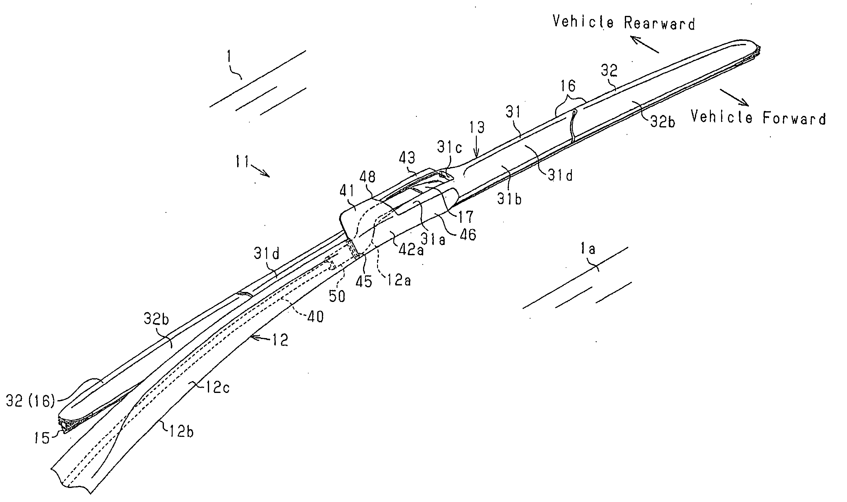
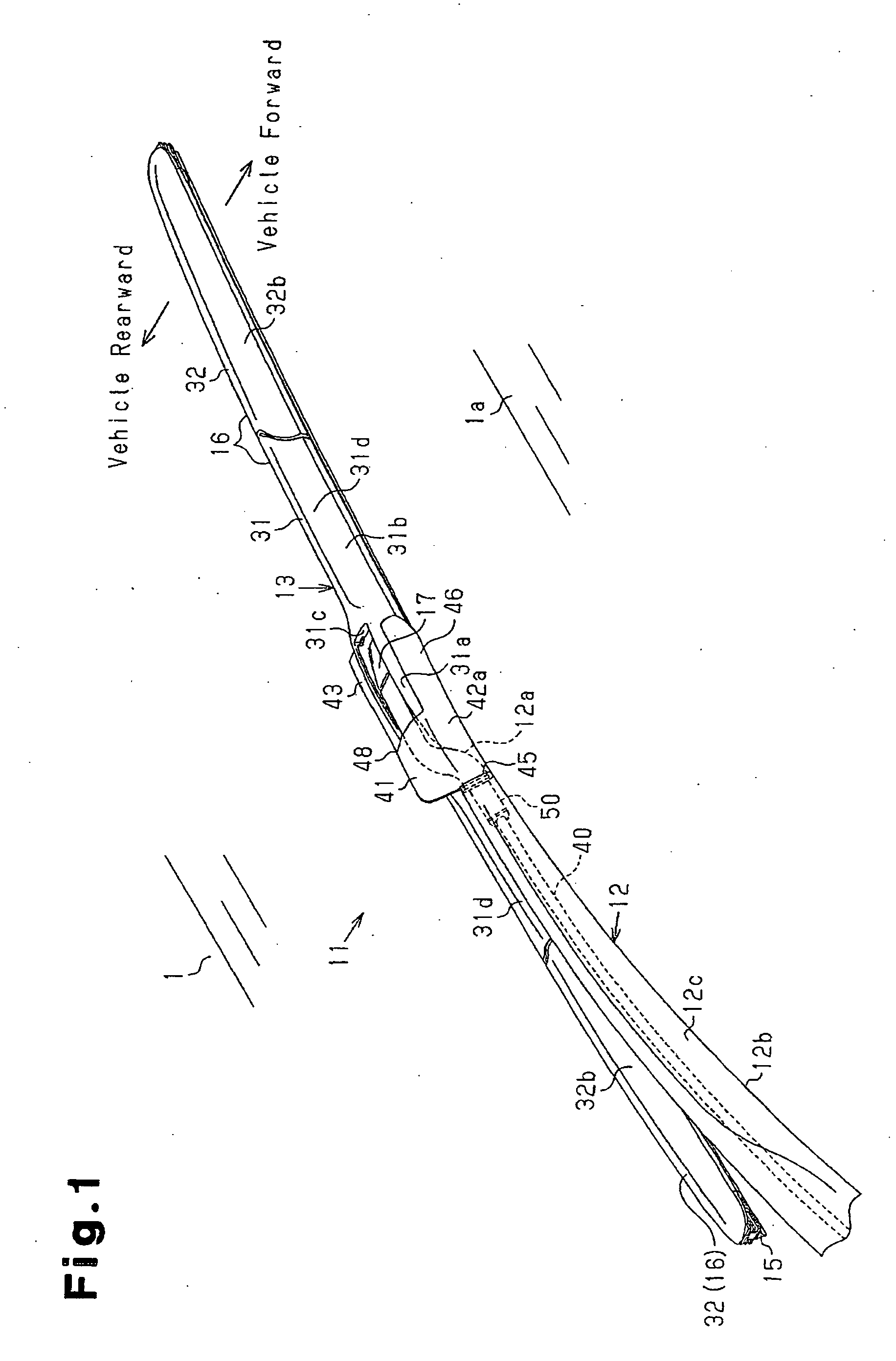
[0021] A vehicle wiper device 11 shown in FIG. 1 wipes dirt and rain droplets from a surface to be wiped 1a of a vehicle windshield 1.

[0022] The vehicle wiper device 11 includes a wiper arm 12, wiper blade 13, and a nozzle mechanism 41 attached to the wiper arm 12. A proximal end of the wiper arm 12 is coupled to a pivot shaft (not shown), which is caused to reciprocate in a predetermined angle range by drive force of a wiper motor (not shown). The wiper blade 13 is rotatably coupled to a distal end of the wiper arm 12. The wiper blade 13 is rotatable about a rotation axis L that extends along the surface to be wiped 1a. The rotation axis L is shown in FIG. 8. A spring (not shown) for pressing the wiper blade 13 against the surface to be wiped 1a is attached to the wiper arm 12 shown in FIG. 1. As the pivot shaft rotates in a reciprocating manner, the wiper arm 12 is caused ...


PUM


Abstract

A pipe member is arranged along a wiper arm. A wiper blade has a lever rotatably coupled to the wiper arm and a blade rubber for wiping a surface to be wiped. A nozzle mechanism has an attachment member attached to the wiper arm, a nozzle member for supplying the washer liquid sent under pressure from the pipe member to the surface to be wiped, and an engaging portion provided in the nozzle member. The attachment member rotatably supports the nozzle member. The engaging portion engages with the wiper blade such that the nozzle member follows rotation of the wiper blade. Therefore, a vehicle wiper device facilitates replacement of the wiper blade, and allows washer liquid to be stably received by the surface to be wiped.

Description

BACK GROUND OF THE INVENTION [0001] The present invention relates to a vehicle wiper device that wipes a surface to be wiped of a vehicle window glass and supplies washer liquid to the surface to be wiped. [0002] Typically, when a wiper blade wipes to wipe dirt from a vehicle window glass, a washing device supplies washer liquid to the surface to be wiped. For example, a wiper device disclosed in Japanese Laid-Open Utility Model Publication No. 54-180541 includes a wiper arm to which a rigid pipe is attached, which properly supplies washer liquid to a surface to be wiped. On an outer side of a wiper blade that is rotatably supported by the wiper arm, the rigid pipe is arranged to extend along the longitudinal direction of the wiper blade. The rigid pipe has a number of spray holes for spraying washer liquid to the surface to be wiped at close range. The wiper blade follows the curved shape of the surface to be wiped. [0003] However, in the above configuration, it is difficult to cau...

Claims


Application Information

Patent Timeline
IPC IPC(8): B60S1/52B60S1/46B60S1/40
CPCB60S1/3806B60S1/3862B60S1/524
Inventor HARITA, YASUHIROHIROTA, YOSHITO
Owner ASMO CO LTD
Features
  • Generate Ideas
  • Intellectual Property
  • Life Sciences
  • Materials
  • Tech Scout
  • Unparalleled Data Quality
  • Higher Quality Content
  • 60% Fewer Hallucinations
Learn More