Windscreen wiper system

a wiper arm and wiper technology, applied in the field of windshield wiper devices, can solve the problems of high cost, high cost, and difficulty in coordinating the force of the required initial stress of the elastic blade with the force of swinging the wiper blade away, so as to achieve the effect of convenient replacement and economic manufactur

Inactive Publication Date: 2011-03-22
ROBERT BOSCH GMBH
View PDF10 Cites 35 Cited by
  • Summary
  • Abstract
  • Description
  • Claims
  • Application Information

AI Technical Summary

Benefits of technology

[0005]The invention attains the stated objective with a windshield wiper device of the type cited at the outset, in which, according to the invention, the elastic blade is arranged in such a way that it can pivot around the fixing element. The pressure force of the wiper arm, which results from the initial stress of the elastic blade, can therefore be well coordinated with the force required to swing the wiper blade away from the window. The elastic blade is designed as a leaf spring that can be stressed for bending so that the wiper blade is pressed against the window during wiper operating by the elastic blade. As a result, it is possible to dispense with the tension spring that has been required until now, thereby reducing the number of components in the inventive windshield wiper device and making it more economical as a result.
[0032]So that the wiper blade can be replaced conveniently, the elastic blade can have a bearing surface, which is adjacent to the fixing element when the wiper arm is swung away from the window.

Problems solved by technology

This variation requires a relatively great number of components and an associated relatively high assembly effort so that costs for this variation are high.
The disadvantage of these types of wiper blades, however, is that it is difficult to coordinate the force for the required initial stress of the elastic blade with the force for swinging the wiper blade away.
As a result, there is a risk that the wiper arm will expectedly swing away from the window if there is a strong air stream or if the vehicle vibrates, e.g., when driving through potholes.

Method used


Image

  • Windscreen wiper system
  • Windscreen wiper system
  • Windscreen wiper system

Examples


Embodiment Construction

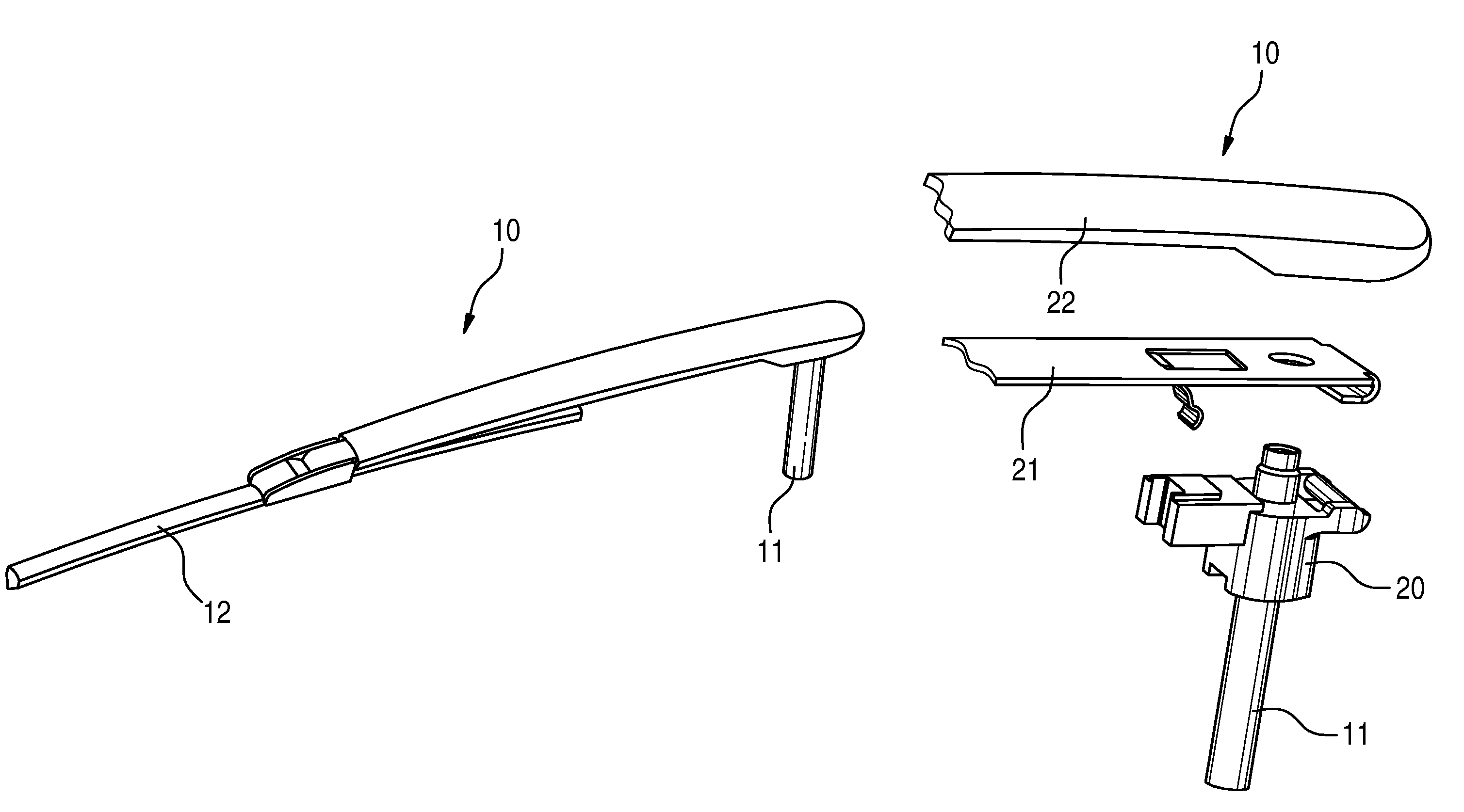
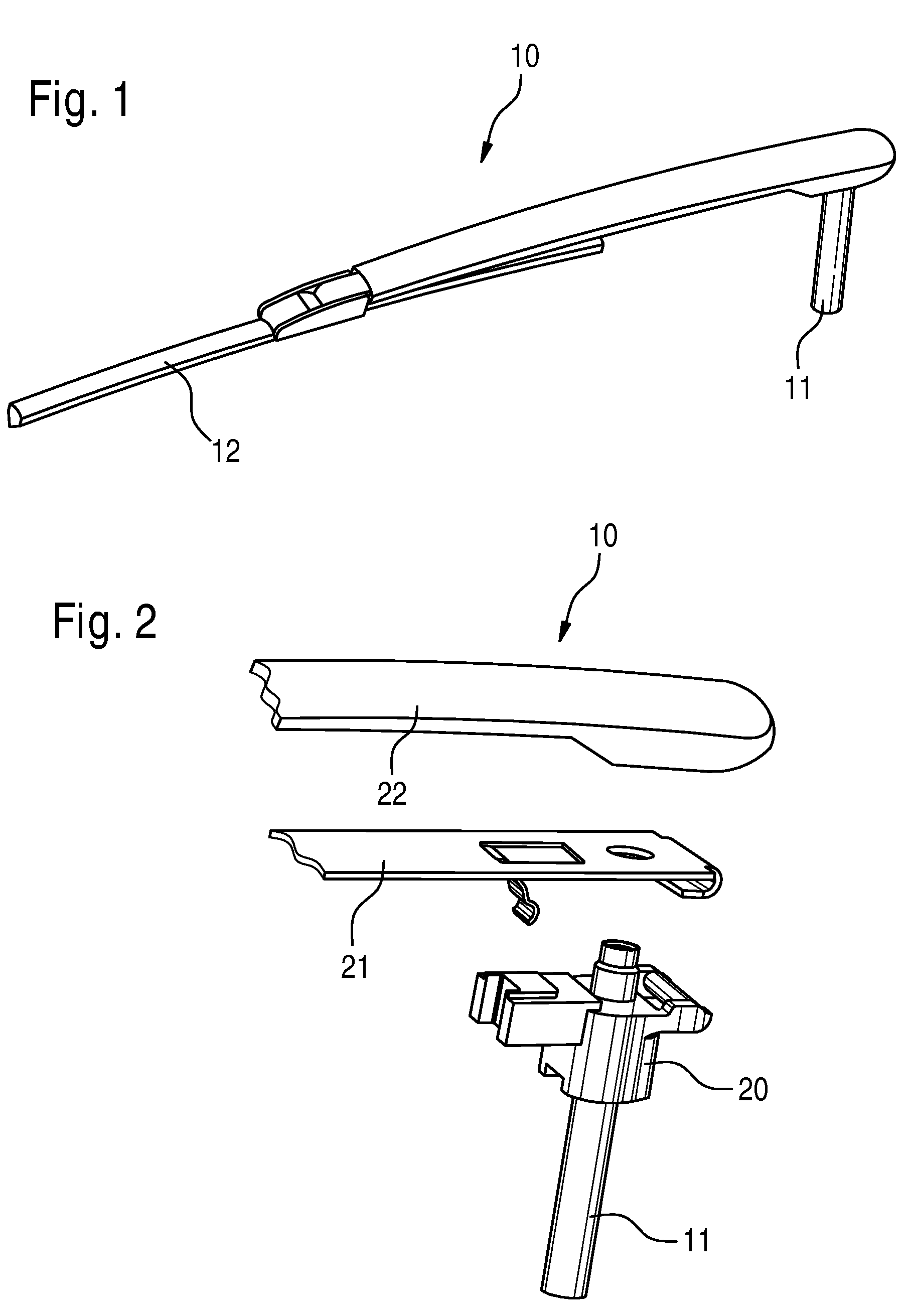
[0050]FIGS. 1 and 2 show a wiper arm 10, which is mounted on a wiper shaft 11 and provided with a wiper blade 12. A fixing element 20 is situated on the wiper shaft 11. An elastic blade 21 can be fastened on the fixing element 20 so that it can pivot and said elastic blade can be covered with a covering 22.

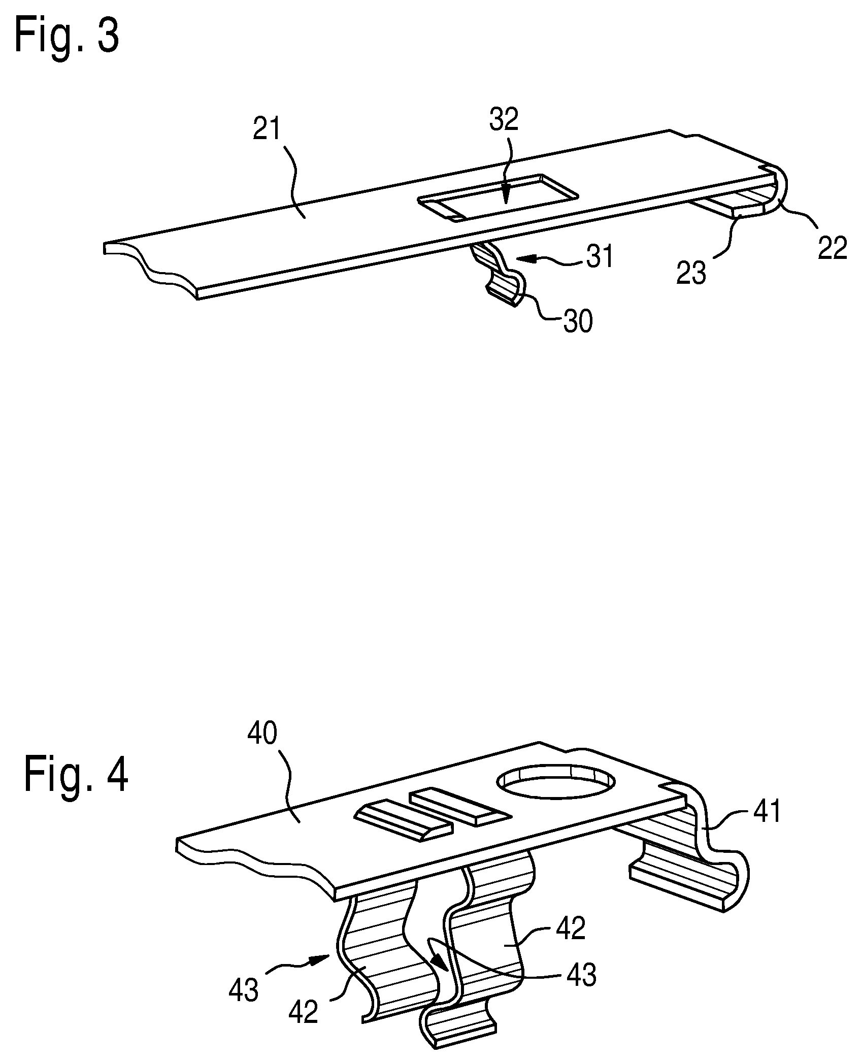
[0051]The elastic blade 21 has a spring clip 30 (see FIG. 3), with which the wiper arm 10 can be locked into an operating position in order to press the wiper blade 12 against a window (not shown here in detail). The spring clip 30 is cut out, preferably punched out of the elastic blade 21 so that the spring clip 30 and the elastic blade 21 can be manufactured as one piece.

[0052]The spring clip 30 is bent on its free end so that it can glide better on the fixing element when the wiper arm 10 pivots (see FIGS. 8 and 9).

[0053]The spring clip 30 also features a crimp 31 (see FIG. 3) in order to lock the wiper arm on the fixing clement (see FIGS. 8 and 9).

[0054]In addition, the elasti...


PUM


Abstract

The invention relates to a windscreen wiper system, in particular for a motor vehicle, comprising at least one wiper arm provided with an elastic blade (21) and a fixing element (60). The known wiper arms comprise a tension spring which presses the wiper blade against a pane along with the windscreen wiper operation and maintains said wiper blade in a folded position with respect to the pane when the wiper blade is changed. Said wiper arms require a relatively important number of components and, for this reason, are relatively expensive. The aim of said invention is to make it possible to produce the windscreen wiper system in a more economical manner. For this purpose, the inventive elastic blade (21) is arranged in such a way that it is pivotable about the fixing element (60).

Description

BACKGROUND OF THE INVENTION[0001]The invention relates to a windshield wiper device, in particular for a motor vehicle, comprising at least one wiper arm provided with an elastic blade and a fixing element.[0002]Wiper arms with a tension spring are known from the prior art, wherein the tension spring presses the wiper arm against the window during wiper operation, and, when the wiper blade is being changed, holds said wiper blade in a position that is swung away from the window. This variation requires a relatively great number of components and an associated relatively high assembly effort so that costs for this variation are high.[0003]In addition, non-articulated wiper arms are also known. These wiper arms have an elastic blade, which is mounted to the fixing element so that it cannot move. In order to swing this wiper arm away from or towards the window, the elastic blade is provided with an initial stress such that starting from a certain distance of the wiper blade from the wi...

Claims


Application Information

Patent Timeline
Patent Type & Authority Patents(United States)
IPC IPC(8): B60S1/34
CPCB60S1/34B60S1/3452B60S1/3454B60S1/3484
Inventor KRAEMER, GODELIEVE
Owner ROBERT BOSCH GMBH
Why Eureka
Try Eureka