Laser marking device

a marking device and laser technology, applied in the direction of distance measurement, mechanical measuring arrangement, instruments, etc., can solve the problems of affecting the cutting accuracy of laser beams, so as to ensure the additional stability, ensure the cutting accuracy, and ensure the cutting straight

Inactive Publication Date: 2007-06-28
ROBERT BOSCH GMBH
View PDF21 Cites 16 Cited by
  • Summary
  • Abstract
  • Description
  • Claims
  • Application Information

AI Technical Summary

Benefits of technology

[0005] A marking device according to the invention having the characteristics of claim 1 has the advantage over the prior art that when this marking device is used, the scribed line that is otherwise required can be dispensed with entirely. Additional aids for drawing the scribed line, such as a goniometer and a ruler, are no longer necessary. With the marking device of the invention, the otherwise required scribed line is replaced entirely by a pointing or marking beam emitted by the laser. Thus a clear line can be reproduced on a workpiece, even over relatively long distances, and along this line the user can saw and thus achieve a straight cut. Even uneven surfaces, where a scribed line is difficult to draw, can now be easily and cleanly machined with the aid of the marking device.
[0006] The marking device is preferably a frame of plastic or metal. The laser, the fastening element, and the goniometer are then located at various places on this frame.
[0007] The laser is preferably designed in the form of an independent component with its own housing. In this housing, there can be at least one laser diode. The inte

Problems solved by technology

A disadvantage of this known circular saw with a laser is that the saw blade, which is downstrea

Method used


Image

  • Laser marking device
  • Laser marking device
  • Laser marking device

Examples


Embodiment Construction

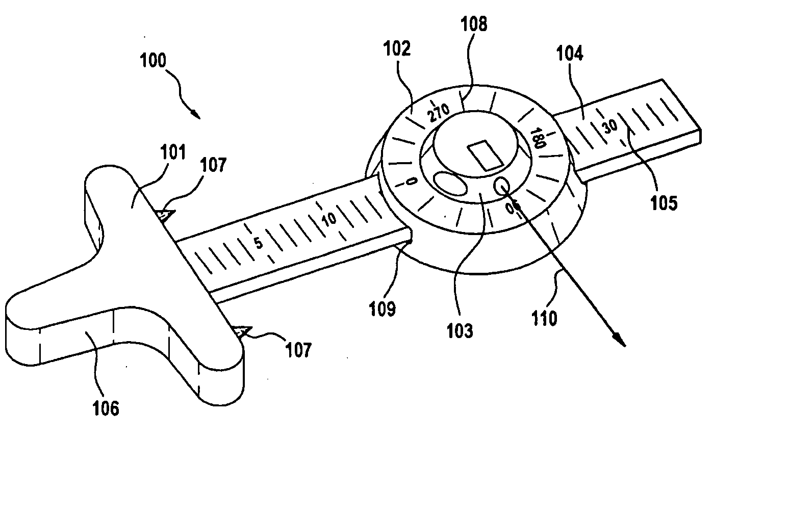
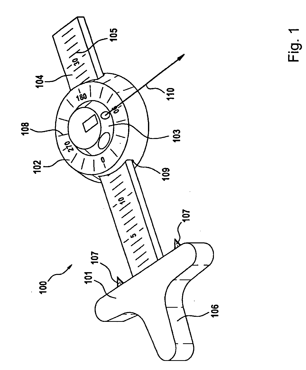
[0039]FIG. 1 shows a first marking device 100. The marking device 100 comprises a parallel stop 101, a protractor or goniometer 102, and a laser 103.

[0040] The parallel stop 101 has a surveyor's rod 104, which has a measurement scale 105 for measuring length. The parallel stop 101 furthermore has a handle 106 with two sharp points 107.

[0041] The protractor 102 is embodied in disklike form and has an angle division 108. The protractor 102 also has a passage 109, through which the surveyor's rod 104 of the parallel stop 101 is guided. As a result, the protractor 102 can be pushed back and forth along the surveyor's rod 104.

[0042] The laser 103 is rotatably supported freely over 360° on the protractor 102. The laser 103 emits a laser beam 110. By rotating the laser 103, the orientation of the laser beam 110 can be varied.

[0043] The mode of operation of the marking device 100 will be described below.

[0044] It is assumed that a user wants to make a straight cut through a wooden boar...


PUM


Abstract

In a marking device having a laser and a fastening element, especially simple, fast and precise marking of workpieces is attained by providing that the marking device includes a goniometer.

Description

PRIOR ART [0001] The invention is based on a marking device having the generic characteristics of claim 1. [0002] Power tools with lasers are known in the prior art. The integrated laser serves as an orienting aid in machining workpieces. [0003] International Patent Disclosure WO 99 / 02310, for instance, discloses a circular saw with a laser element integrated in the handle. This laser element generates a line in the sawing direction on the workpiece to be machined. The line predetermined by the laser beam serves the circular saw user as an orientation in sawing. The laser beam is made as much as possible to coincide with a scribed line drawn in advance, for instance. [0004] A disadvantage of this known circular saw with a laser is that the saw blade, which is downstream of the laser beam, can drift away from the scribed line. Precise cutting is thus not guaranteed. Moreover, the laser beam is merely an orienting aid in sawing. In actuality, a user of the circular saw, who with it wa...

Claims


Application Information

Patent Timeline
IPC IPC(8): G01C15/00B25H7/00
CPCB25H7/00G01C15/002Y10S33/21G01B5/24G01B5/245
Inventor DELFINI, STEFANOGERBER, BEATACKERMANN, CHRISTIAN
Owner ROBERT BOSCH GMBH
Why Eureka
Try Eureka