Terminal fitting

a technology of fittings and fittings, applied in the field of fittings, can solve problems such as the bulkyness of therectangular tube, and achieve the effect of reducing the height of the tub

Active Publication Date: 2007-06-28
SUMITOMO WIRING SYST LTD
View PDF15 Cites 5 Cited by
  • Summary
  • Abstract
  • Description
  • Claims
  • Application Information

AI Technical Summary

Benefits of technology

[0007] The invention relates to a terminal fitting having a tube for receiving a mating terminal. The tube includes a bottom plate, first and second side plates projecting from the opposite lateral edges of the bottom plate, and a upper plate extending from the distal end of the first side plate having an extending end in direct or indirect contact with the distal end of the second side plate. The terms bottom and upper are used herein as a convenient frame of reference, and are not intended to imply a required gravitational orientation. The upper plate has at least one embossment projecting in to define a step or recess. At least one pressing portion extends from the distal edge of the second side plate and is placed in contact with the outer surface of the embossment to prevent an outward movement of the upper plate. Thus, the height of the tube can be reduced by a recessed dimension of the embossment.

Problems solved by technology

This construction has a problem of making the rectangular tube bulky because the upper plate and the pressing portion are placed one over the other.

Method used


Image

  • Terminal fitting
  • Terminal fitting
  • Terminal fitting

Examples


first embodiment

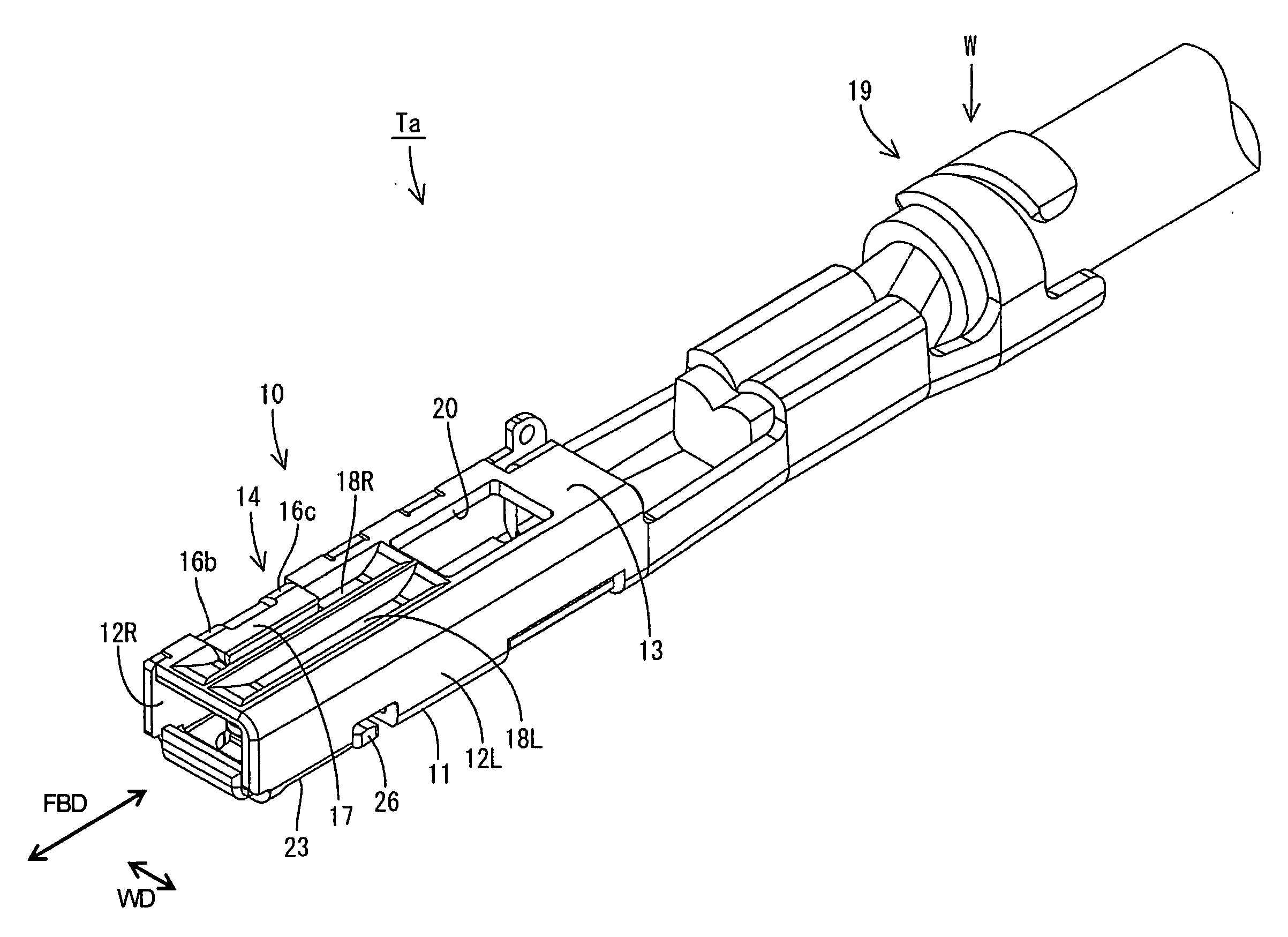
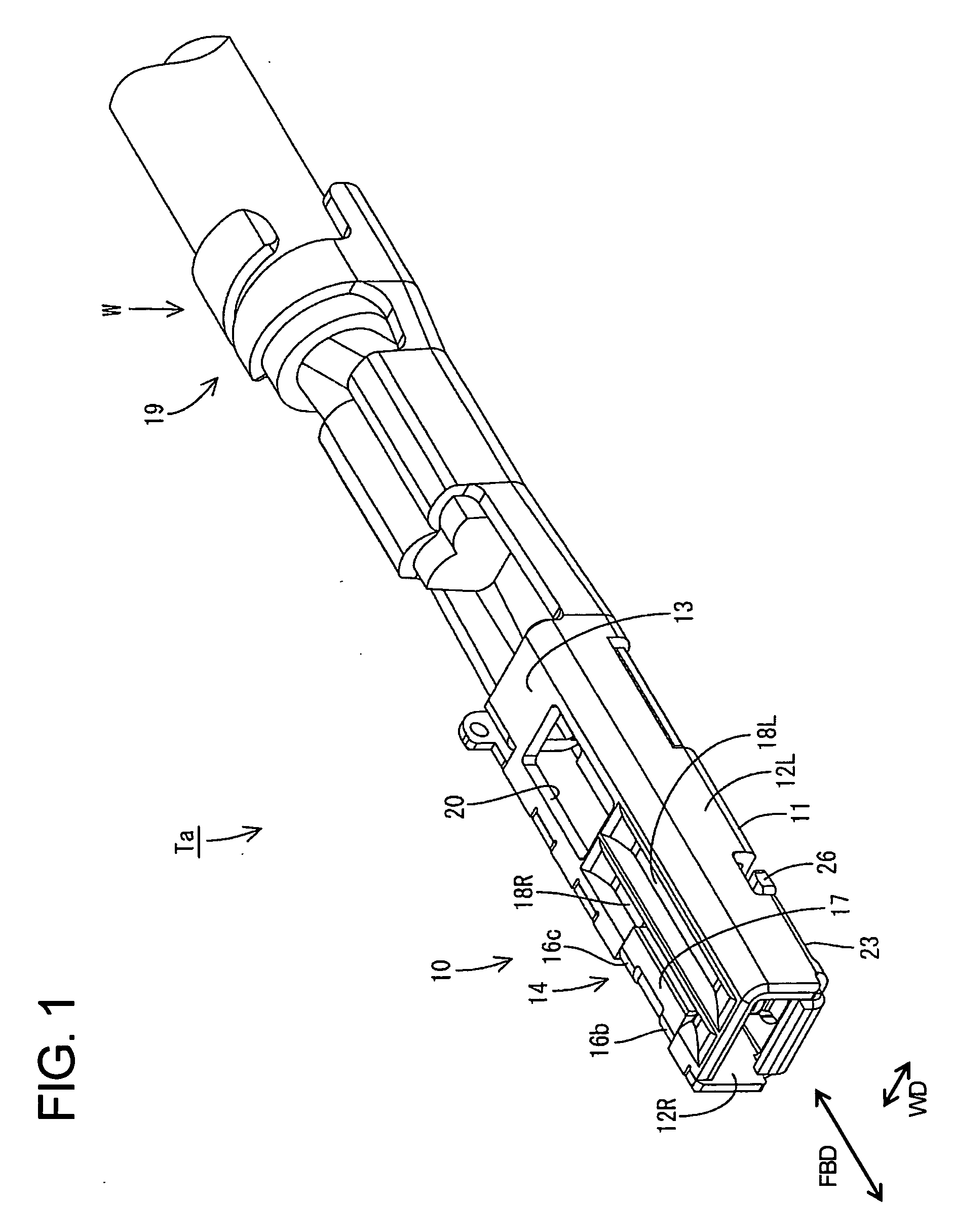
[0037] A terminal fitting according to the invention is identified by Ta in FIGS. 1 to 8. The terminal fitting Ta is formed by punching and / or cutting a conductive metal plate material P into a specified shape and then bending, folding, embossing, cutting and / or pressing the metal plate material P to define the terminal fitting Ta that is long and narrow and long in forward and backward directions FBD. A rectangular tube 10 is formed at the front of the terminal fitting Ta and is hollow in forward and backward directions FBD. A crimping portion 19 is defined at a rear and has open barrels that can be crimped, bent or folded into connection with a wire W.

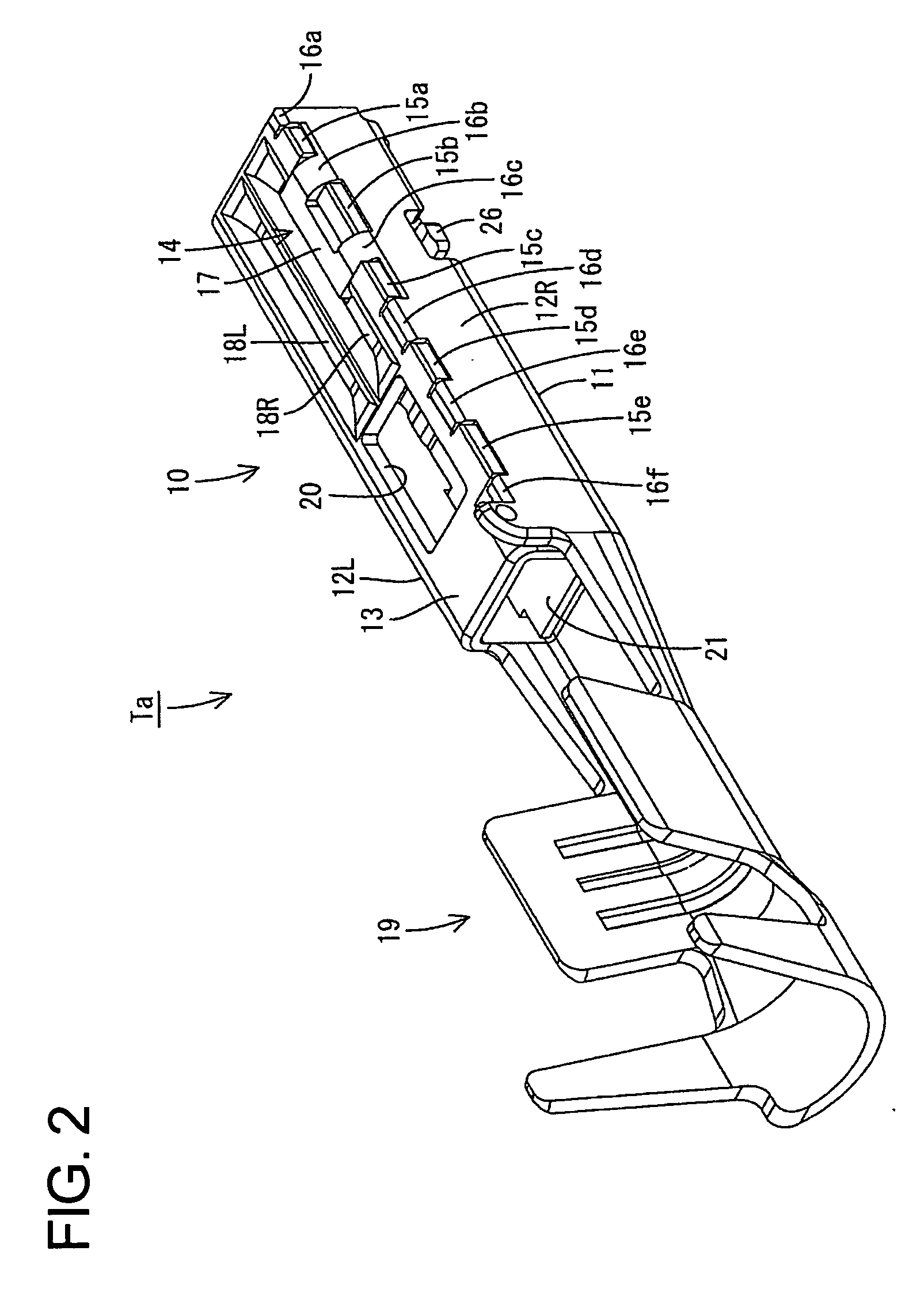
[0038] The tube 10 has a substantially rectangular cross-section defined by a bottom plate 11, a left side plate 12L, a right side plate 12R, an upper plate 13 and a pressing portion 14. The bottom plate 11 is narrow and long in forward and backward directions FBD. The left and right side plates 12L and 12R also are long and narrow i...

second embodiment

[0054] The terminal fitting Tb of the second embodiment is inserted upside down into a cavity 41 in a connector housing 40. A resiliently deformable lock 42 is cantilevered forward along the bottom surface of the cavity 41. The upper plate 13 of the rectangular tube 10 deforms the lock 40 down and out during the insertion process. However, the lock 42 is restored resiliently when the terminal fitting Tb is inserted completely so that a retaining projection 42a on the upper surface of the lock 42 engages the front edge of a locking hole 20. The terminal fitting Tb is retained by this engagement (see FIG. 13).

[0055] A withdrawal jig (not shown) can be inserted from the front to push the leading end of the lock 42 out down to withdraw the inserted terminal fitting Tb. Thus, the lock 42 is disengaged from the locking hole 20 to free the terminal fitting Tb from the retained state. The terminal fitting Tb then may be pulled backward while keeping the lock 42 deformed.

[0056] Because of m...

fourth embodiment

[0062] The crimping portion 60 of the fourth embodiment has an insulation barrel 61 with left and right crimping pieces 61L, 61R to be crimped, bent or folded into connection with an insulation coating Wa of a wire W, and a wire barrel 62 having left and right crimping pieces 63 to be crimped, bent or folded into connection with a core Wb exposed by stripping the insulation coating Wa of the wire W. The left and right crimping pieces 61L, 61R of the insulation barrel 61 are offset in forward and backward directions FBD to locate the right crimping piece 61L behind the left crimping piece 61L when the crimping pieces 61L, 61R are crimped, bent or folded around the wire W.

[0063] A backward pulling force acts on the wire W acts on the insulation barrel 61. The right and rearward crimping piece 61R resists most of drag against the pulling force. A load resulting from this pulling force is taken into account in this embodiment, and the width WR of the right and rearward crimping piece 61...


PUM


Abstract

A rectangular tube (10) is formed such that a pair of side plates (12L, 12R) stand up from the opposite left and right edges of a bottom plate (11) and an extending end of an upper plate (13) extending from the upper edge of the left side plate (12L) substantially in parallel with the bottom plate is placed in contact with the upper end surface of the right side plate (12R). The upper plate (13) has an embossment (18R) projecting in and a pressing portion (14) extending from the upper edge of the right side plate (12R) is placed into contact with the upper surface of the embossment (18R) to prevent an upward movement of the upper plate (13). Thus, the height of the rectangular tube (10) can be reduced by a recessed dimension of the embossment (18R).

Description

BACKGROUND OF THE INVENTION [0001] 1. Field of the Invention [0002] The invention relates to a terminal fitting. [0003] 2. Description of the Related Art [0004] Japanese Unexamined Patent Publication No. 2003-092161 discloses a terminal fitting having a rectangular tube with a bottom plate. First and second side plates stand up at right angles from the opposite first and second edges of the bottom plate. An upper plate extends from the upper edge of the first side plate substantially in parallel with the bottom plate, and the extending end of the upper plate contacts the upper end surface of the second side plate. [0005] A terminal fitting of this kind may also have a pressing portion extending from the upper edge of the second side plate and substantially parallel to the bottom plate. The pressing portion is placed on the upper surface of the upper plate to prevent an upward movement of the upper plate. This construction has a problem of making the rectangular tube bulky because th...

Claims


Application Information

Patent Timeline
Patent Type & Authority Applications(United States)
IPC IPC(8): H01R13/11
CPCH01R13/11H01R43/16H01R13/04H01R13/42
Inventor SHIMIZU, TOORU
Owner SUMITOMO WIRING SYST LTD
Why Eureka
Try Eureka