Heat pipes utilizing load bearing wicks

Inactive Publication Date: 2007-07-05
TOUZOV IGOR VICTOROVICH
View PDF18 Cites 35 Cited by
  • Summary
  • Abstract
  • Description
  • Claims
  • Application Information

AI Technical Summary

Problems solved by technology

Applications of heat pipes often become impractical due to complexity associated with fitting these components into tightly packed spaces or because of mobility restrictions they could cause.
Liquid crystallization might severely damage the shell of a heat pipe.
Devices of the other two inventions fail to account for high air permea

Method used


Image

  • Heat pipes utilizing load bearing wicks
  • Heat pipes utilizing load bearing wicks
  • Heat pipes utilizing load bearing wicks

Examples


Embodiment Construction

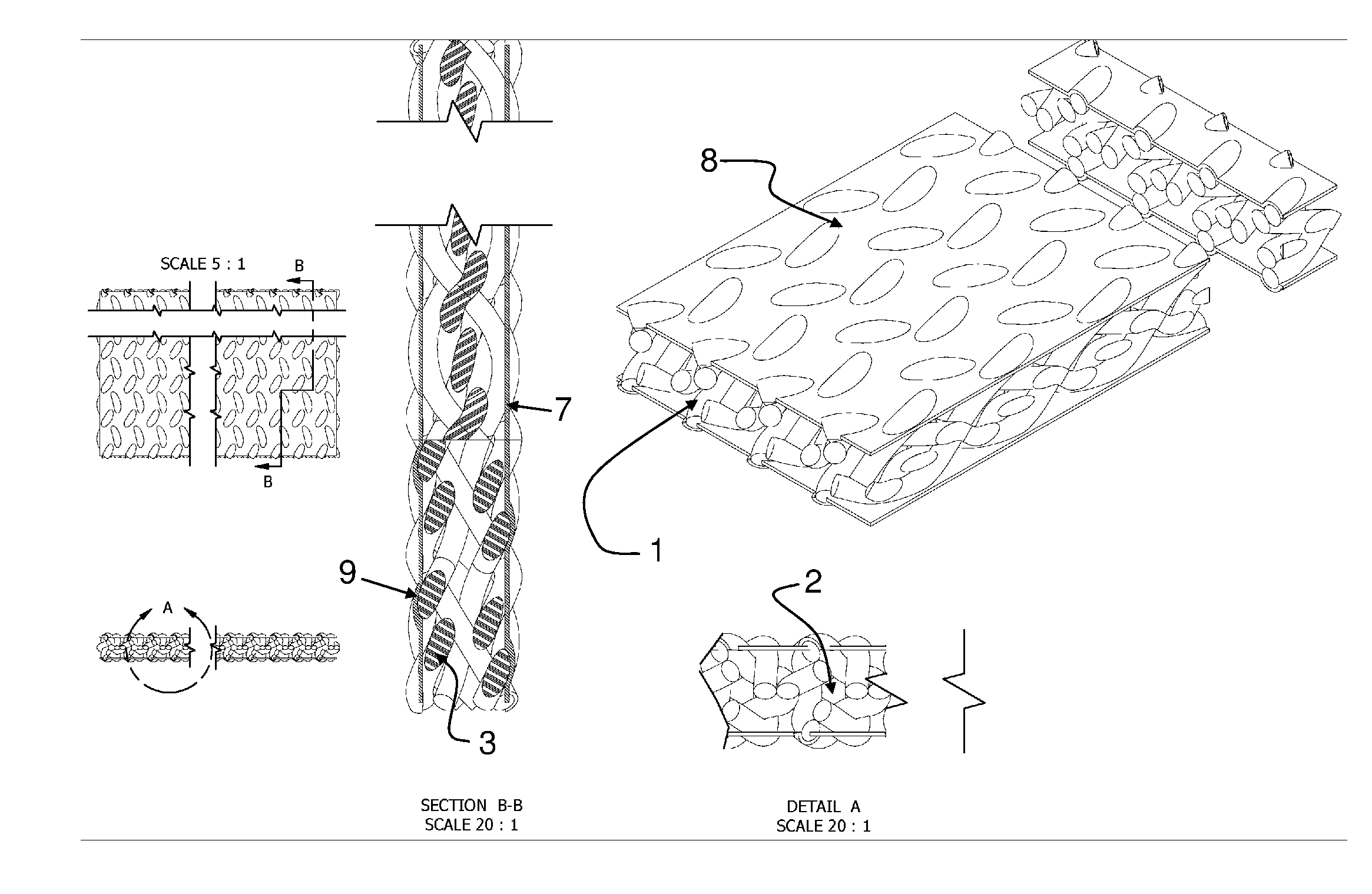
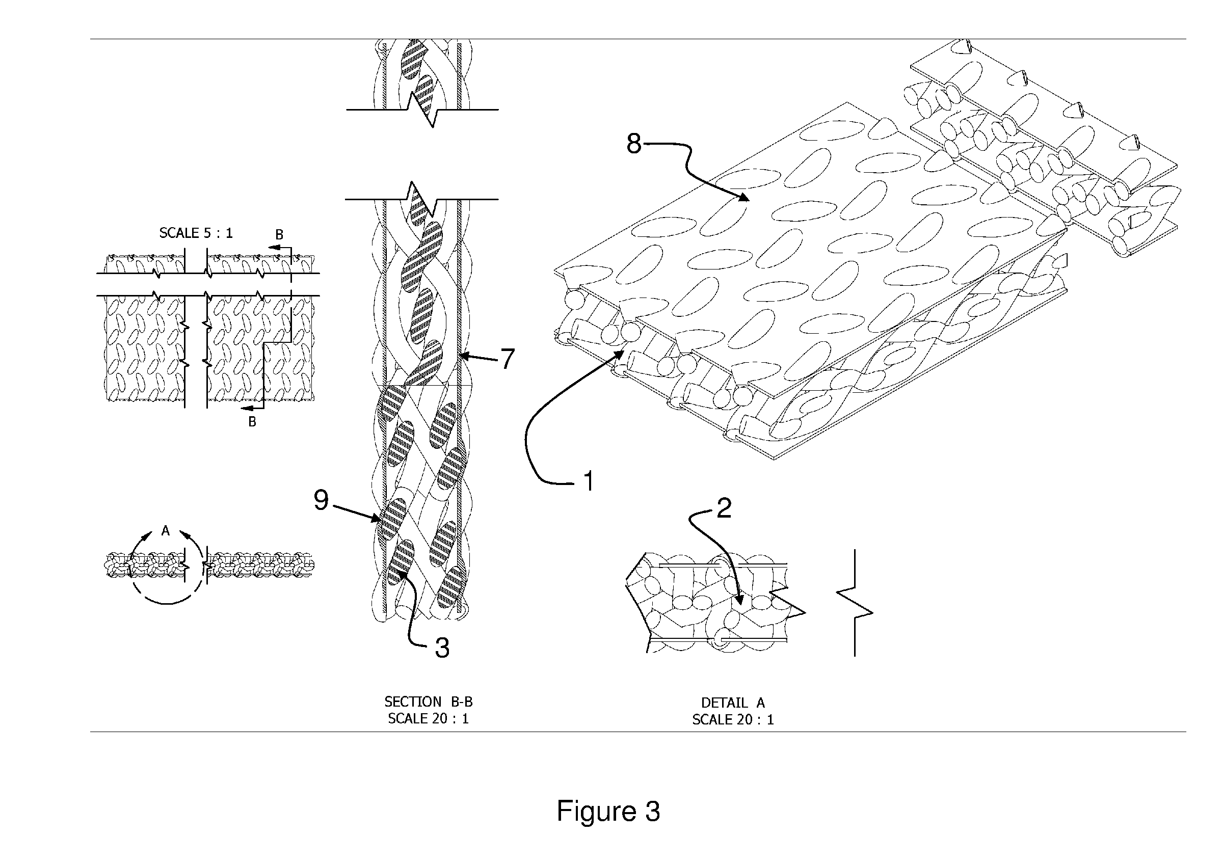
[0006] This invention overcomes cited technical challenges utilizing a soft shell and a load bearing wick structure in a heat pipe design. Unlike competitive technologies it provides convenient topological solution for compact designs, confined spaces, and flexible solutions.

Wick

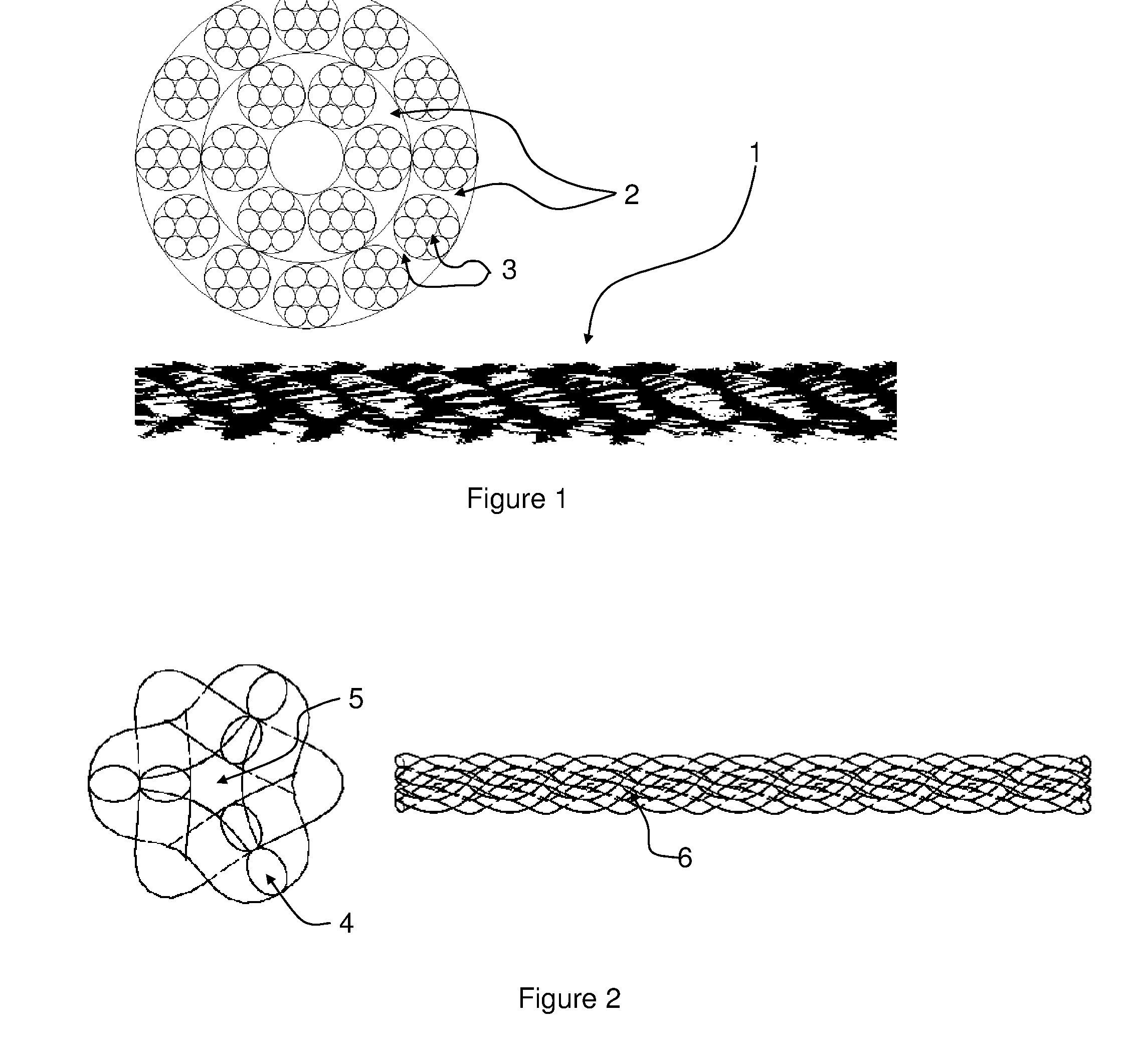
[0007]FIG. 1 shows schematic the structure of the wick. Preferred embodiment of the invention uses a wick 1 is formed by braided fiber. The yarns are braided to form plaits along preferred direction of the pipe. Each yarn could be formed by braided fiber or tows. 6-tow maypole braided construction is a good example for one of many possible yarn designs.

[0008] The total wick structure accounts for small (capillary 3) and large (passages 2) gaps. The capillary are formed by fiber-fiber gaps and inner-yarn tubes, Inner yarn tube is formed when small number of carriers (4-8) are used in rotary or maypole braiding. The passages are formed by yarn-yarn and braid-braid spacing. This construction has high mechan...


PUM


Abstract

This invention enables mechanical design of flexible and elastic heat pipes. It provides structural solution that reduces weight/performance ratio for traditional heat pipes and prevents freeze damages.

Description

FIELD OF THE INVENTION [0001] This invention relates to a field of structural design of heat pipes. It provides functional solution that reduces weight / performance ratio for traditional heat pipes and improves performance of flexible heat pipe designs. PRIOR ART [0002] Applications of heat pipes often become impractical due to complexity associated with fitting these components into tightly packed spaces or because of mobility restrictions they could cause. Another implication is that systems can be utilized at temperatures below freezing point of selected liquid. Liquid crystallization might severely damage the shell of a heat pipe. It also disables pipe functions until the liquid melts. Prior art (U.S. Pat. No. 4,194,559) exploit compromise solutions that prevent freeze damage of the pipe in expense of added free volume that increases total volume and weight of a solution. [0003] Prior art (U.S. Pat. Nos. 4,279,294, 5,647,429, and 6,595,270) include attempts to utilize polymer mat...

Claims


Application Information

Patent Timeline
IPC IPC(8): F28D15/00
CPCF28D15/0241F28F19/006F28D15/046
Inventor TOUZOV, IGOR VICTOROVICH
Owner TOUZOV IGOR VICTOROVICH
Why Eureka
Try Eureka