Apparatus for mounting a flat screen display device to a lift mechanism

a technology for flat screen display devices and lift mechanisms, which is applied in the direction of stand/trestles, cabinetry, show hangers, etc., can solve the problems of difficult mounting of flat screen display devices on the lift, expensive and time-consuming procedures, etc., and achieves convenient installation and maintenance, simple installation, and continuous adjustment of position

Inactive Publication Date: 2007-07-05
BOBER WIESLAW
View PDF11 Cites 21 Cited by
  • Summary
  • Abstract
  • Description
  • Claims
  • Application Information

AI Technical Summary

Benefits of technology

[0007] Another object of the present invention is to provide new and improved apparatus for mounting a flat screen display device to a lift which provides continuous adjustability of the position of the flat screen display device on the lift as well as a simplified installation of the flat screen device to the lift that requires less manpower than has been required by, and which is faster than, conventional mounting apparatus.

Problems solved by technology

One of the difficulties in housing a flat screen display device in a cabinet on a lift for selective elevation and retraction from and back into the cabinet is the mounting of the flat screen device in an appropriate position on the lift so that when the lift is fully extended the display device is situated at the proper height for viewing.
While these mounting apparatus provide an adjustable mounting of the flat screen display device on a lift mechanism for enabling the device to be positioned most advantageously for viewing, the mounting of the flat screen display device on the lift is still difficult due to the heavy and bulky nature of flat screen displays and the necessity of holding the device adjacent to the lift so that the holes in the flanges of the fastener assemblies align with the slots in the vertical members to enable the bolts to be inserted and tightened.
This is an expensive and time-consuming procedure.

Method used


Image

  • Apparatus for mounting a flat screen display device to a lift mechanism
  • Apparatus for mounting a flat screen display device to a lift mechanism
  • Apparatus for mounting a flat screen display device to a lift mechanism

Examples


Embodiment Construction

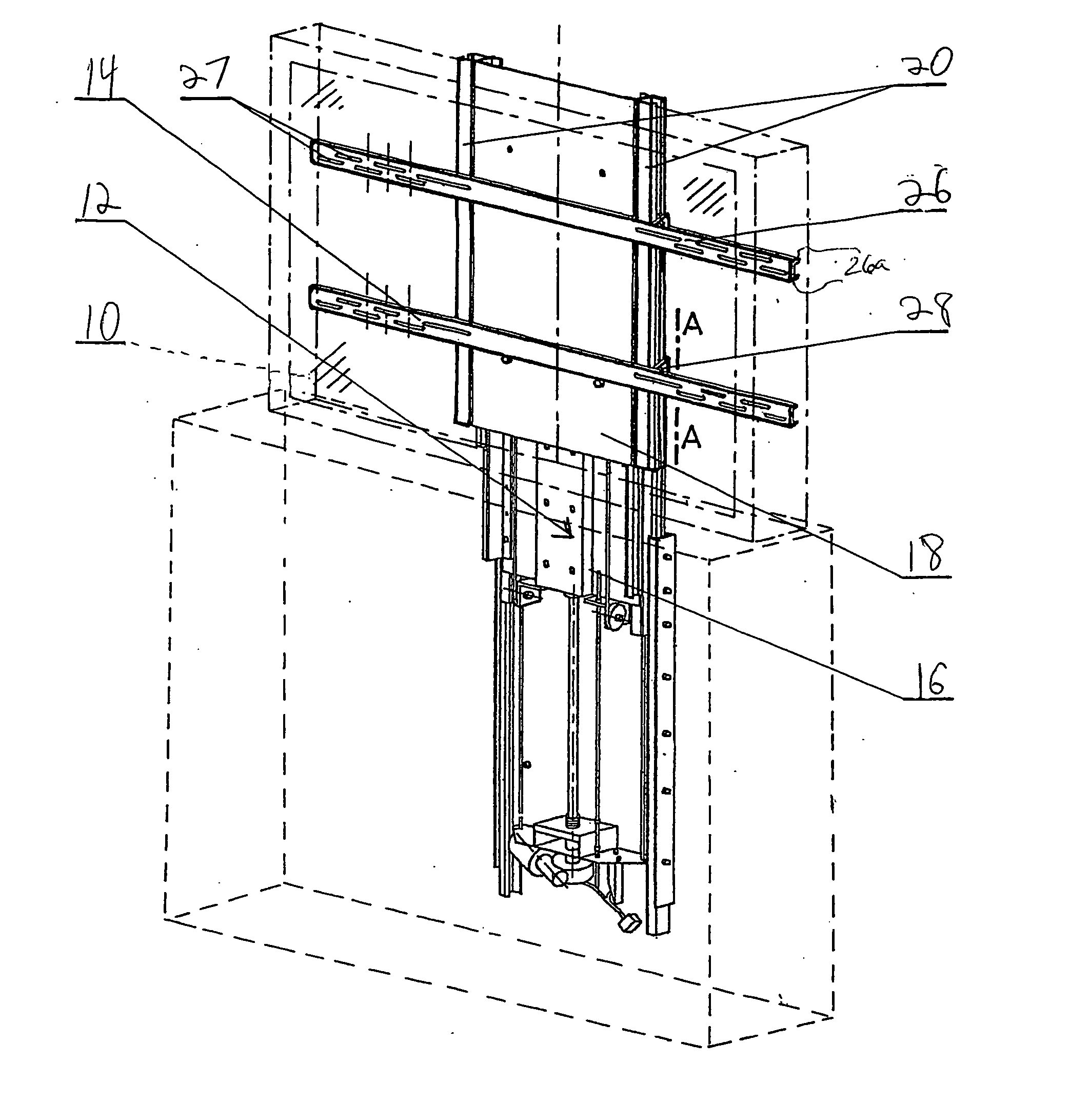
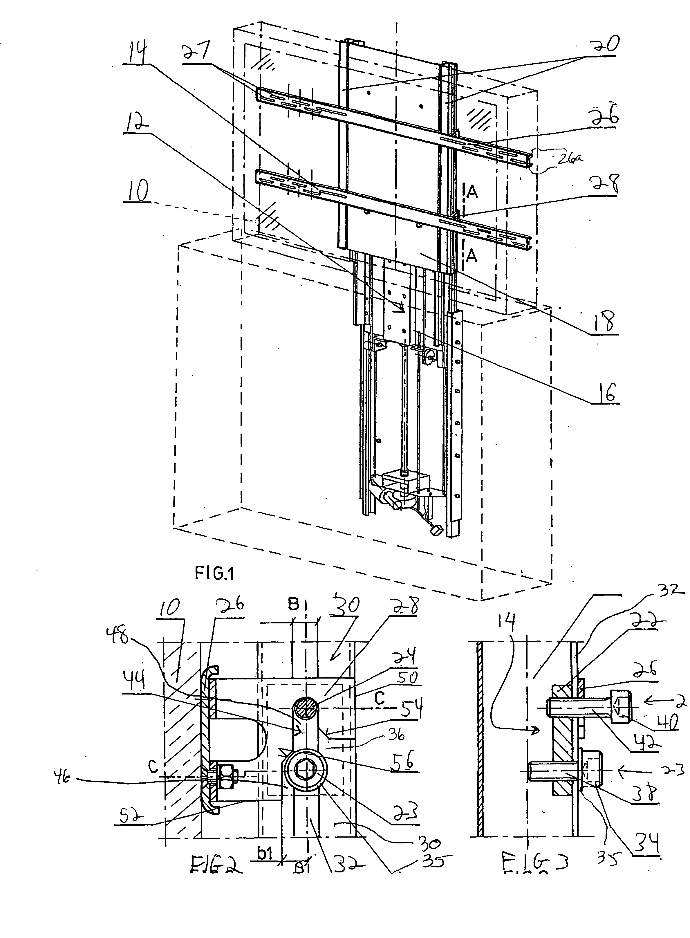
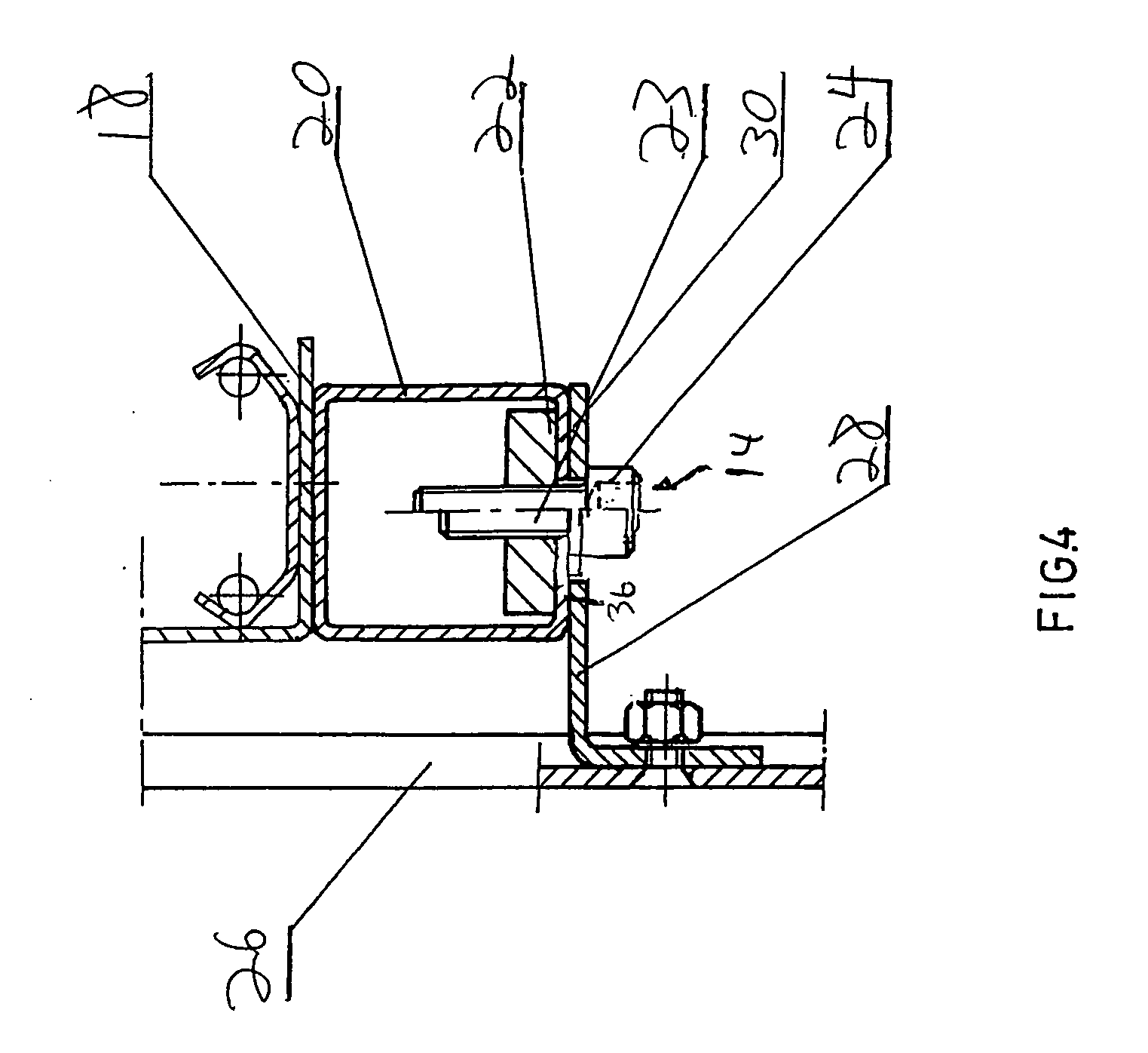
[0015] Referring now to the drawings in which like reference characters designate identical or corresponding parts throughout the several views, a preferred embodiment of the invention will now be described with reference to FIGS. 1-4. FIG. 1 shows a flat screen display device 10 (shown in phantom for purposes of clarity) affixed to a vertical lift mechanism generally designated 12, via apparatus, generally designated 14, of the present invention. The vertical lift mechanism 12 can be any conventional lift of the type known in the art. As illustrated, the lift mechanism 12 has a telescopic construction including at least a screw activated base unit 16 and a pulley activated support unit 18. Two vertical tubular members 20 are situated at the lateral sides of the support unit 18. It is understood, however, that the apparatus 5 may be used in conjunction with a wide variety of vertical lifts.

[0016] Referring now to FIGS. 1 and 2, the apparatus 14 is adapted to connect the display dev...


PUM


Abstract

A mounting apparatus for affixing a flat screen display device to a vertical lift mechanism having vertical guide members situated at the lateral sides of a lift including at least one pair of mounting members, at least one pair of hanging members, at least one elongate support member, and at least one pair of bracket members. Each mounting member of the pair is affixed to a respective one of the pair of vertical tubular members at an adjustable position thereon in substantially horizontal alignment with the other mounting member of the pair. Each hanging member of the pair is affixed to a respective one of the mounting members. The at least one elongate support member is adapted for connection to mounting components at the rear of the flat screen display device and structured and arranged to extend substantially horizontally when the display device is mounted to the tubular members of the lift mechanism. The at least one pair of bracket members are affixed in spaced relationship to the at least one support member and each bracket member of a pair is structured and arranged to receive a respective one of the pair of hanging members.

Description

FIELD OF THE INVENTION [0001] The present invention generally relates to vertical lift mechanisms, and in particular, to apparatus for affixing a flat screen device to a vertical lift mechanism. BACKGROUND OF THE INVENTION [0002] It has become common to house flat screen display devices, such as LCD or plasma televisions, within cabinets and to extend the device outside the cabinet via a lift mechanism when it is desired to view the display device and then retract it back into the cabinet when viewing is completed. [0003] One of the difficulties in housing a flat screen display device in a cabinet on a lift for selective elevation and retraction from and back into the cabinet is the mounting of the flat screen device in an appropriate position on the lift so that when the lift is fully extended the display device is situated at the proper height for viewing. Since flat screen devices are made in a wide range of sizes, and the distances between the mounting components, usually situat...

Claims


Application Information

Patent Timeline
Patent Type & Authority Applications(United States)
IPC IPC(8): A47F5/00
CPCA47B81/061F16M11/24F16M11/30F16M11/046F16M11/18F16M11/04
Inventor BOBER, WIESLAWKISLICH, HENRY
Owner BOBER WIESLAW
Why Eureka
Try Eureka