Eureka AIR delivers breakthrough ideas for toughest innovation challenges, trusted by R&D personnel around the world.

Multiplexed amplifier

Active Publication Date: 2007-07-05
NORTHROP GRUMMAN SYST CORP
View PDF14 Cites 9 Cited by
  • Summary
  • Abstract
  • Description
  • Claims
  • Application Information

AI Technical Summary

Benefits of technology

[0007] Preferably, the amplifier structure uses superconducting components, which facilitate narrowband filtering and perform amplification and upconversion with minimal power dissipation. Moreover, because the amplifier is capable of multiplexing a large number input signals onto a single output line, power dissipation that results from using multiple connection lines is avoided.

Problems solved by technology

Low operating temperatures dictate low available cooling power on the sensor or detector stage of these low-temperature cameras.
Both these prior art techniques are significantly limited because only 32 pixels per amplifier may be multiplexed, and there is still a need to dissipate power in the SQUID circuitry.

Method used


Image

  • Multiplexed amplifier
  • Multiplexed amplifier
  • Multiplexed amplifier

Examples


Embodiment Construction

[0018] As shown in the drawings for purposes of illustration, the present invention is concerned with a multiplexer / amplifier structure that can multiplex the outputs of a large number of detector elements, and thereby dissipate very little power. Prior approaches to reducing power dissipation by multiplexing have been limited in the number of sensor pixels that can be multiplexed in one amplifier, and have been accordingly limited in their effectiveness.

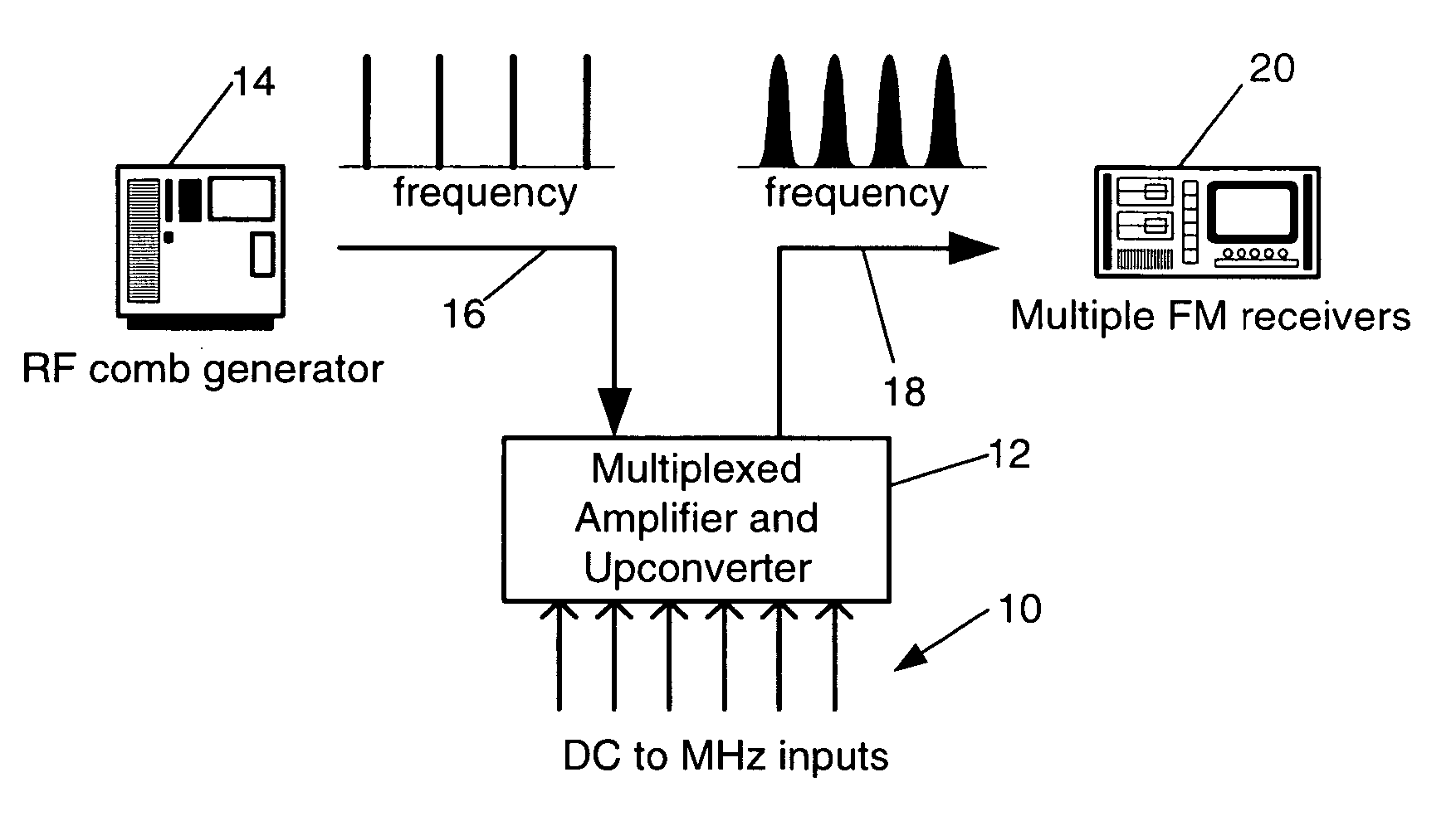
[0019] In accordance with the present invention, these limitations of the prior art have been overcome and the invention facilitates multiplexing of a large number, such as a hundred or more, of low-frequency signals simultaneously onto a single transmission line, while dissipating only a small amount of electrical power.

[0020]FIG. 1 depicts the principle of the invention. An array of input signals, indicated at 10, is received from a source such as an array of detector elements in an X-ray or millimeter-wave camera (not shown). E...


PUM


Abstract

Multiple sensor signals are used to modulate an equal number of frequency-spaced carrier signals in a directional parametric upconverting amplifier. Basically, the carrier signals are separated in a cascaded or parallel configuration of narrow frequency passbands, which also modulate the carrier signals with low-frequency sensor signals. The modulated carrier signals are multiplexed and output over a single signal path, thereby reducing power dissipation. Preferably implemented in superconducting circuitry, the multiplexed amplifier facilitates multiplexing of as many as hundreds of sensor signals and achieves both amplification and upconverting with minimal dissipation of power.

Description

[0001] This invention was made with Government support under Subagreement Number SA3315. The Government has certain rights in this invention.BACKGROUND OF THE INVENTION [0002] This invention relates generally to multiplexed amplifiers and, more particularly, to multiplexed amplifiers that operate at very low temperatures and are suitable for use on a space platform. Various X-ray and millimeter-wave cameras are under development for use in earth observation and space exploration. The most sensitive of these cameras are cryogenic. If the detector elements of a camera can be cooled below 1° Kelvin, the thermal mass of the individual pixels can be reduced to such a degree that individual photons can be detected by the resulting temperature rise of the corresponding detector elements. [0003] Low operating temperatures dictate low available cooling power on the sensor or detector stage of these low-temperature cameras. In a detector stage having thousands of pixels, meeting these cooling...

Claims


Application Information

Patent Timeline
IPC IPC(8): H03F3/38
CPCH01P1/2135
Inventor SMITH, ANDREW D.ALLEN, BARRY R.
Owner NORTHROP GRUMMAN SYST CORP
Why Eureka
Eureka Blog
Learn More