
Electro-optic display with edge seal

a technology of optical display and edge seal, which is applied in the direction of non-linear optics, static indicating devices, instruments, etc., can solve the problems of inadequate service life of these displays, preventing their widespread use, and gas-based electrophoretic media appearing to be susceptible to the same types of problems

Active Publication Date: 2007-07-05
E INK CORPORATION
View PDF5 Cites 134 Cited by
  • Summary
  • Abstract
  • Description
  • Claims
  • Application Information

AI Technical Summary

Benefits of technology

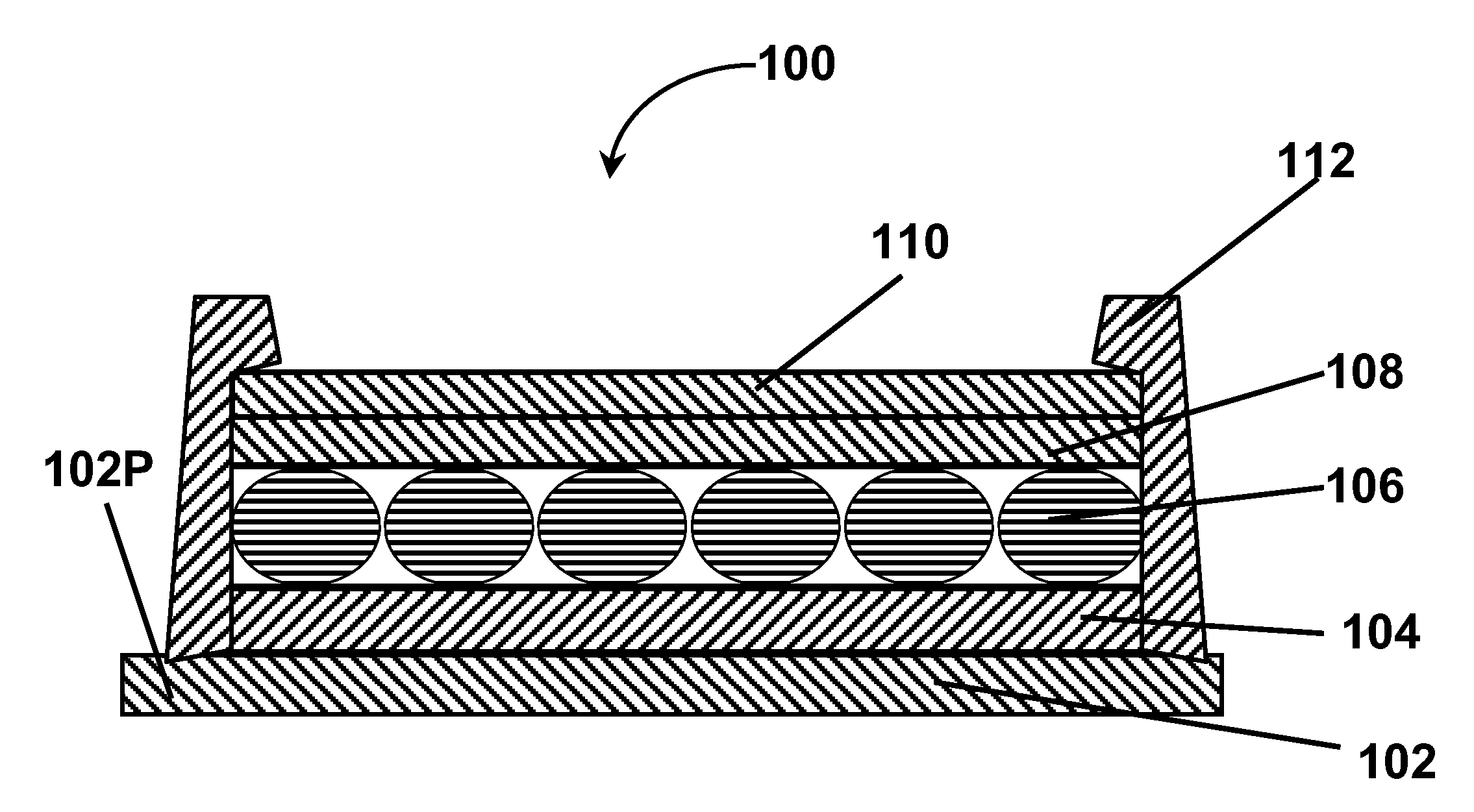
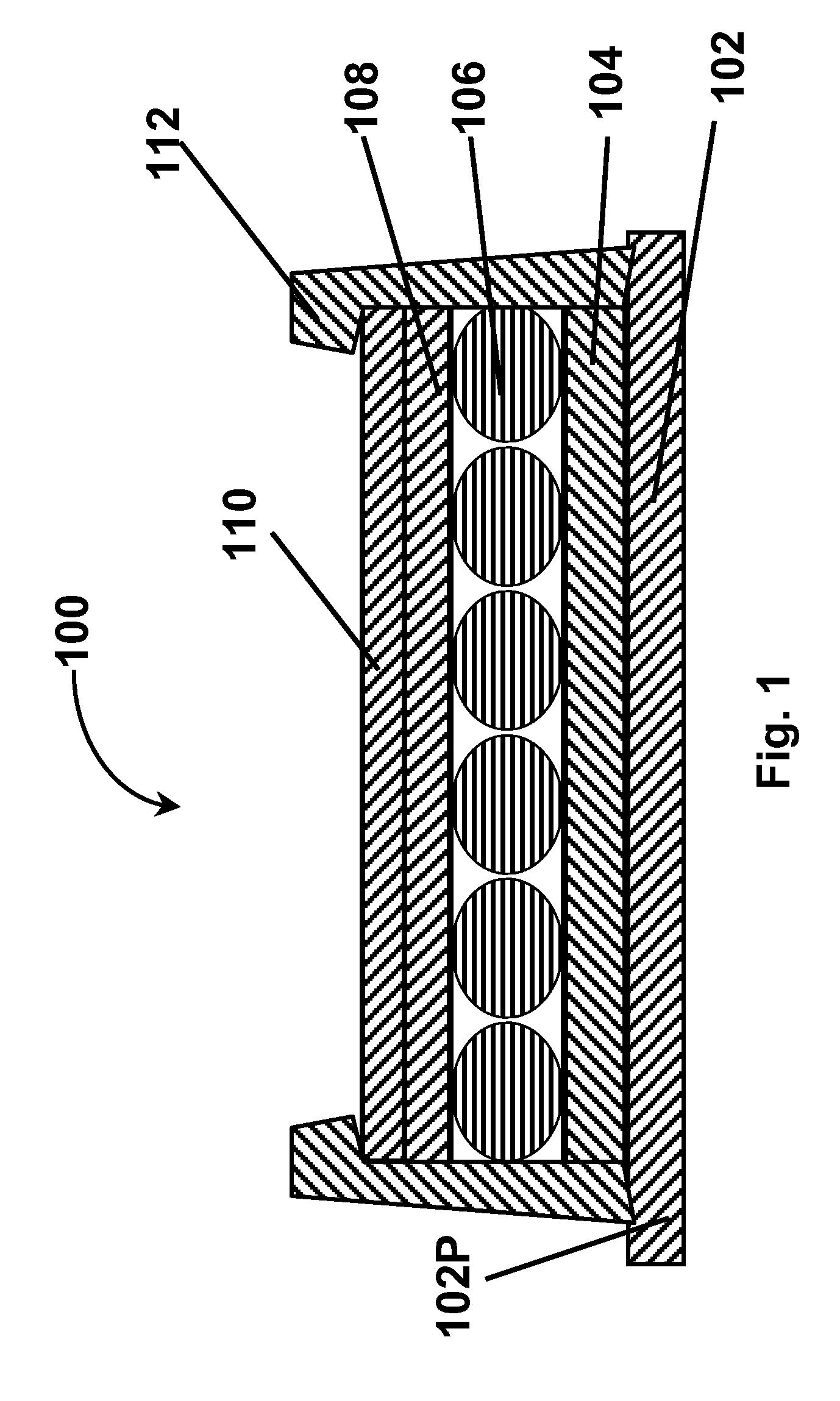
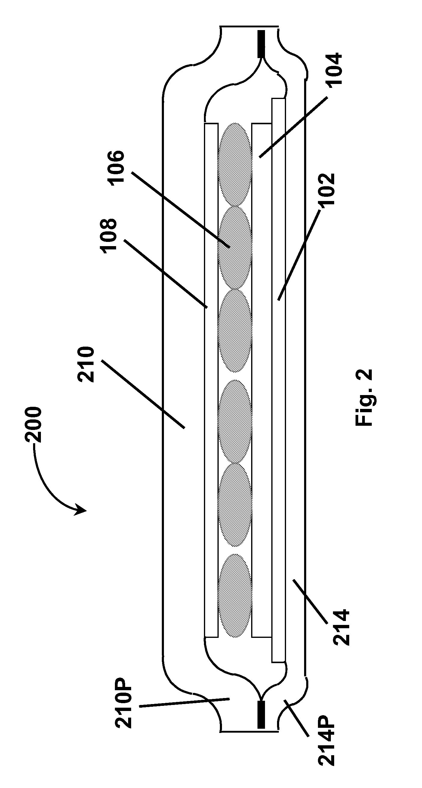
The present invention provides an electro-optic display with a layer of electro-optic material that is smaller in size than the backplane, leaving a peripheral portion of the backplane extending beyond the edges of the layer of electro-optic material. A protective layer is also included to prevent ingress of material from the environment into the electro-optic material. The display can be sealed using a sealing material that extends from the peripheral portion of the backplane to the exposed viewing surface of the protective layer. The invention also provides a double sealed protective sheet display and a single sealed protective sheet display. The technical effects of the invention include improved durability and reliability of the display, as well as better protection against environmental factors.

Problems solved by technology

Nevertheless, problems with the long-term image quality of these displays have prevented their widespread usage.
For example, particles that make up electrophoretic displays tend to settle, resulting in inadequate service-life for these displays.
Such gas-based electrophoretic media appear to be susceptible to the same types of problems due to particle settling as liquid-based electrophoretic media, when the media are used in an orientation which permits such settling, for example in a sign where the medium is disposed in a vertical plane.
Indeed, particle settling appears to be a more serious problem in gas-based electrophoretic media than in liquid-based ones, since the lower viscosity of gaseous suspending fluids as compared with liquid ones allows more rapid settling of the electrophoretic particles.
However, the methods used for assembling LCD's cannot be used with solid electro-optic displays.
This LCD assembly process cannot readily be transferred to solid electro-optic displays.
Electro-optic displays are often costly; for example, the cost of the color LCD found in a portable computer is typically a substantial fraction of the entire cost of the computer.
However, such equipment is costly and the areas of electro-optic media presently sold may be insufficient to justify dedicated equipment, so that it may typically be necessary to transport the coated medium from a commercial coating plant to the plant used for final assembly of electro-optic displays without damage to the relatively fragile layer of electro-optic medium.
The aforementioned type of edge seal, and similar edge seals, are not suitable for use in flexible displays since the edge seal itself imparts rigidity to the display.

Method used


Image

  • Electro-optic display with edge seal
  • Electro-optic display with edge seal
  • Electro-optic display with edge seal

Examples


Embodiment Construction

[0129] Flexible, including rollable, electro-optic displays, especially those using encapsulated electrophoretic media, present important new marketing opportunities; for example, large displays which can be stored in a compact form may be useful as additional display devices on electronic devices which are presently equipped only with a small display screen but where a larger display screen would often be useful; examples of such devices include cellular telephones equipped to receive electronic mail. However, such flexible electro-optic displays will typically require sealing to prevent the ingress of water vapor and other environmental contaminants which can adversely affect the electro-optic properties or operating lifetime of the display. The aforementioned U.S. Pat. Nos. 6,982,178 and 7,110,164 and Patent Publication No 2004 / 0155857 all discuss the sealing of electro-optic displays, but most of the displays there considered are rigid, being formed on glass or similar backplane...


PUM

PropertyMeasurementUnit
diameteraaaaaaaaaa
thicknessaaaaaaaaaa
thicknessaaaaaaaaaa

Abstract

Various types of edge seals for protecting electro-optic displays against environmental contaminants are described. In one type of seal, the electro-optic layer is sandwiched between a backplane and a protective sheet and a sealing material extends between the backplane and the protective sheet. In other seals, the protective sheet is secured to the backplane or to a second protective sheet adjacent the backplane. The electro-optic layer can also be sealed between two layers of adhesive or between one layer of adhesive and the backplane. Other seals make use of flexible tapes extending around the periphery of the display.

Description

REFERENCE TO RELATED APPLICATIONS [0001] This application claims benefit of copending Application Ser. No. 60 / 597,801, filed Dec. 20, 2005. [0002] This application is a continuation-in-part of copending application Ser. No. 10 / 907,065, filed Mar. 18, 2005 (Publication No. 2005 / 0146774), which is itself a divisional of application Ser. No. 10 / 249,957, filed May 22, 2003 (now U.S. Pat. No. 6,982,178), which itself claims benefit of Application Ser. No. 60 / 319,300, filed Jun. 18, 2002, and of Application Ser. No. 60 / 320,186, filed May 12, 2003 [0003] This application is also related to: [0004] (a) copending application Ser. No. 10 / 605,024, filed Sep. 2, 2003 (Publication No. 2004 / 0155857), which claims benefit of Application Ser. No. 60 / 319,516, filed Sep. 3, 2002; [0005] (b) application Ser. No. 10 / 904,063, filed Oct. 21, 2004 (now U.S. Pat. No. 7,110,164), which is a continuation-in-part of the aforementioned application Ser. No. 10 / 605,024, and claims benefit of Application Ser. Nos...

Claims


Application Information

Patent Timeline
Patent Type & Authority Applications(United States)
IPC IPC(8): G09G3/34G02F1/167G02F1/1679
CPCG02F1/133305G02F1/1339G02F1/161G02F1/155G02F2201/50G02F1/0107G02F1/167G02F1/1679
Inventor DANNER, GUY M.PATRY, SHAMUS FORDHONEYMAN, CHARLES HOWIEWHITESIDES, THOMAS H.MCCREARY, MICHAEL D.DUTHALER, GREGG M.
Owner E INK CORPORATION
Learn More