[0071] An
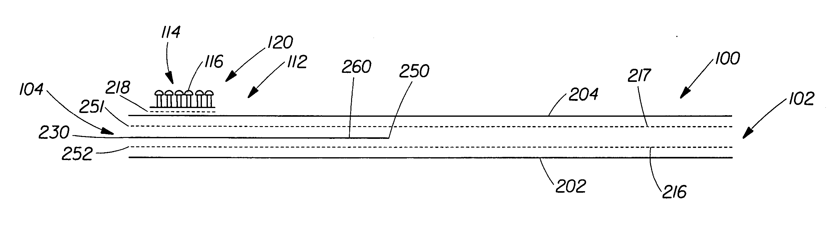
advantage of the present invention is that the first portion 260 of the stiffening element 230 is disposed between and is joined to the first substrate 202 and to the second substrate 204. Because the first portion 260 is joined to the first substrate 202 and to the second substrate 204, edges of the first portion 260 are secured between the first substrate 202 and the second substrate 204. So, the edges of the stiffening element 230 are less likely to be exposed when the fastening member is under tension.
[0072] The first portion width 280 can be of any suitable size. For example, in some embodiments, the first portion width 280 can be greater than about 2% of the intermediate zone width 133. In some embodiments, the first portion width 280 can be between about 2% and 100% of the intermediate zone width 133 or any individual number within the range. In some embodiments, the first portion width 280 can be between about 10% and 75% of the intermediate zone width 133. In some embodiments, the first portion width 280 can be between about 25% and 50% of the intermediate zone width 133. In some embodiments, the first portion width 280 may be greater than or equal to the fastening element width 132 in addition to the intermediate zone width 133. In some embodiments, the first portion width 280 can be equal to an end region width. In some embodiments, the first portion width 280 can be greater than about 1 mm and less than or equal to about 50 mm or any individual number within the range. In some embodiments, the first portion width 280 can be greater than or equal to about 4 mm and less than or equal to about 35 mm. In some embodiments, the first portion width 280 can be greater than or equal to about 8 mm and less than or equal to about 25 mm.
[0073] In some embodiments, under a tension of between 1.5 N / cm and 4.0 N / cm, edges of the stiffness element 230 in the first portion 260 are exposed less than about 1 mm. In some embodiments, the edges of the stiffness element 230 have an exposed edge
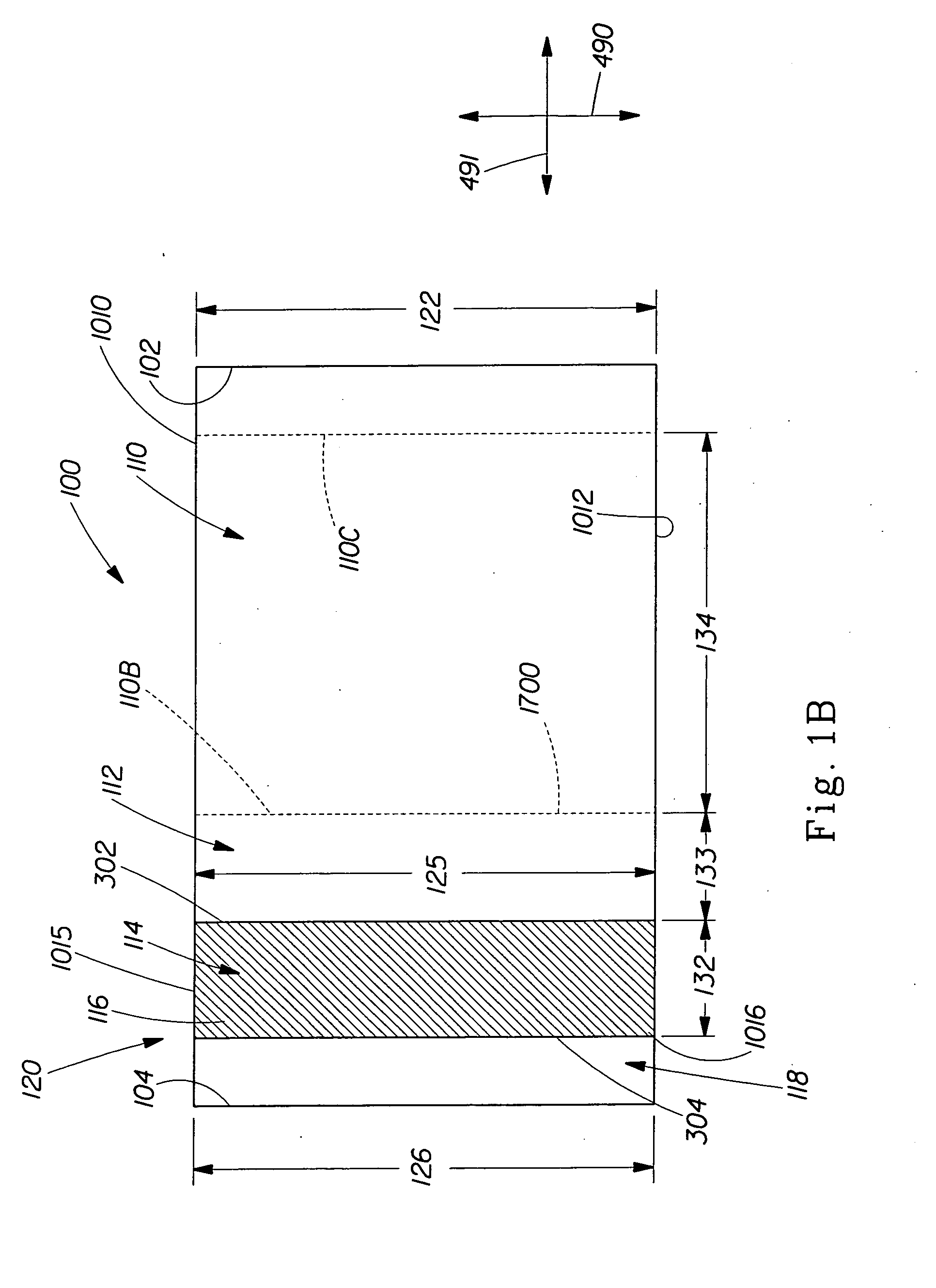
length measurement of less than about 2 mm. As shown in FIG. 8, exposed edge length is the maximum distance generally parallel to the first direction 490 between a first edge 1018 of the stiffening element 230 and the
leading edge 1010. Alternatively, exposed edge length can be the maximum distance generally parallel to the first direction 490 between a second edge 1017 of the stiffening element 230 and the
trailing edge 1012. The test method for measuring exposed edge length is hereafter. In some embodiments, the edges of the stiffness element 230 in the first portion 260 are exposed less than about 0.5 mm. In some embodiments, the edges of the stiffness element 230 have an exposed edge length of less than about 0 mm.
[0074] In some embodiments, a ratio of the amount of exposed edges of the stiffness element 230 to the end region length 125 defines an
exposure ratio and can be between about 0% to about 10% or any individual number within the range. In some embodiments, the
exposure ratio can be less than or equal to about 5%. In some embodiments, the
exposure ratio can be less than or equal to about 3%. In some embodiments, the exposure ratio can be less than or equal to about 2%. In some embodiments, the exposure ratio can be less than or equal to about 1%.
[0075] In some embodiments, a exposure ratio of the amount of exposed edges of the stiffness element 230 to the fastening element length 126 can be between about 0% to about 10% or any individual number within the range. In some embodiments, the exposure ratio can be less than or equal to about 5%. In some embodiments, the exposure ratio can be less than or equal to about 3%. In some embodiments, the exposure ratio can be less than or equal to about 2%. In some embodiments, the exposure ratio can be less than or equal to about 1%.
[0076] As stated previously, the panel region can be elastically extensible in some embodiments. In embodiments where the panel region is elastically extensible, a fastening member constructed in accordance with the present invention may comprise an elastomeric element. An example of such an embodiment is discussed with regard to FIG. 3.

