Monocular PD ruler

Inactive Publication Date: 2007-07-12
DUMAIS DAVID G
View PDF13 Cites 15 Cited by
  • Summary
  • Abstract
  • Description
  • Claims
  • Application Information

AI Technical Summary

Problems solved by technology

However, existing PD rulers suffer from several disadvantages.
In addition, when utilizing these existing

Method used


Image

  • Monocular PD ruler
  • Monocular PD ruler
  • Monocular PD ruler

Examples


Embodiment Construction

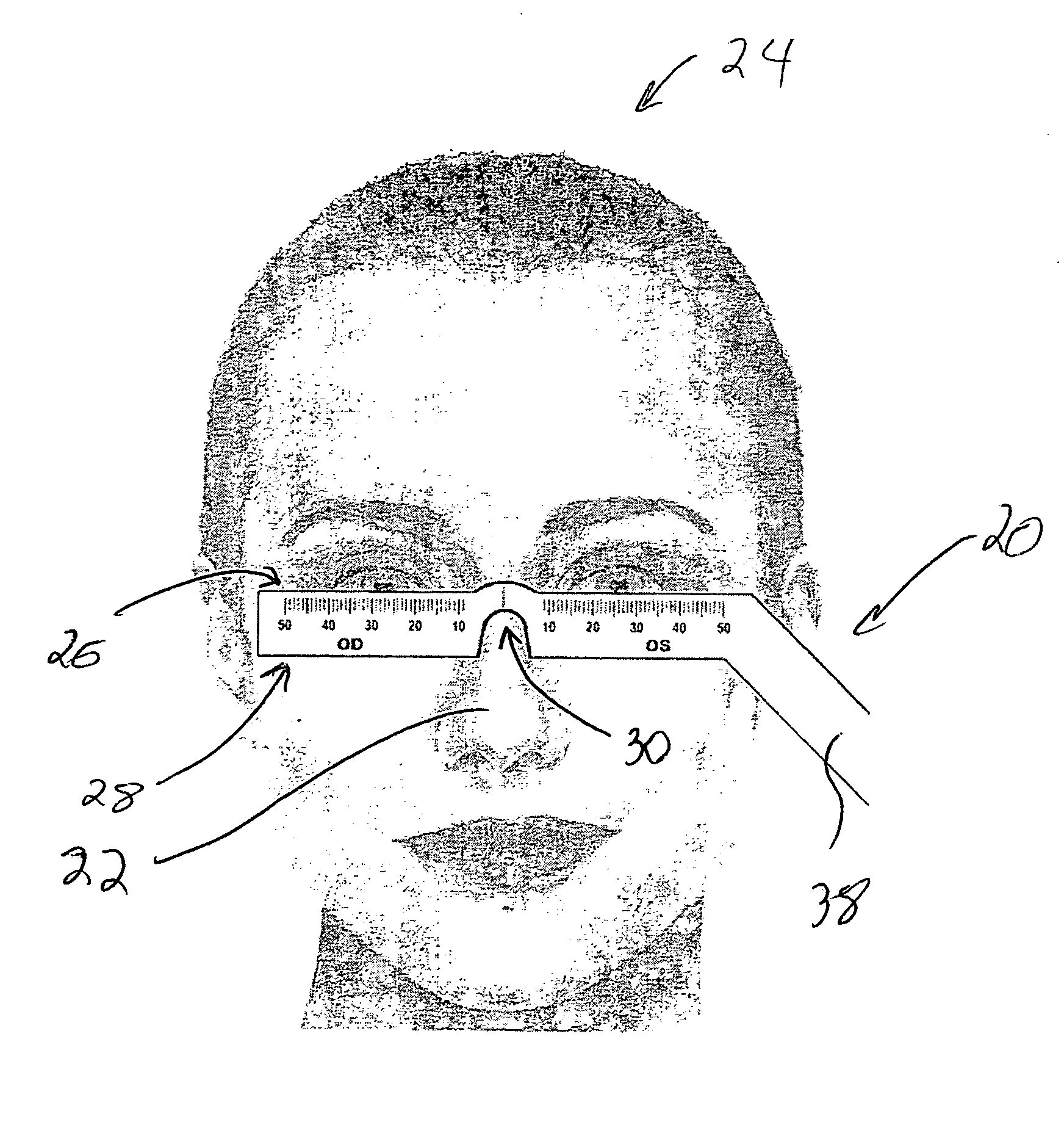
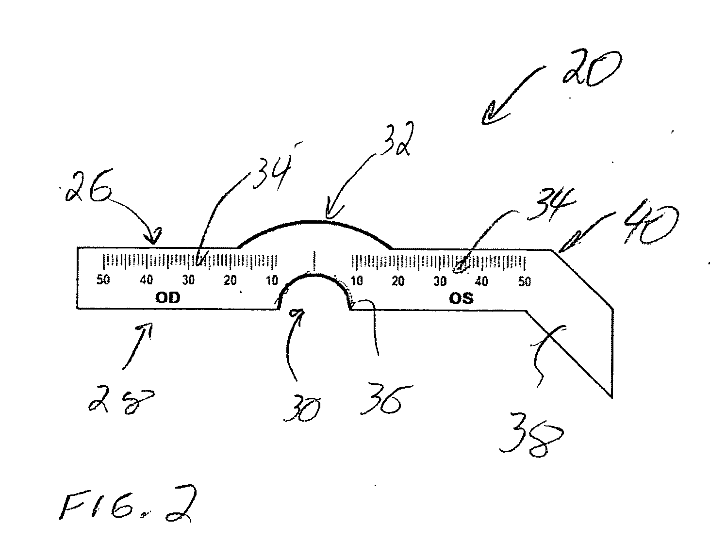
[0011] A monocular ruler for measuring the PD of a person utilized in fitting prescription eye glasses is disclosed. FIG. 2 is a front view of a PD ruler 20 in the preferred embodiment of the present invention. FIG. 3 is a front view of the PD ruler of FIG. 2 positioned upon the nose 22 of a person 24. The PD ruler includes an upper edge 26 and a lower edge 28. The lower edge includes a bridge 30 sized for positioning upon the nose of the person. The bridge is located at a center point 32 of the ruler. At the center point, indicia 34 are positioned at regular intervals outwardly from the center point. In the preferred embodiment of the present invention, the indicia are millimeter marks. Thus, from the center point, the marks run sequentially outward (e.g., 0-50 mm on the left side and 0-50 mm on the right side). The OD denotes placement over the person's right eye while the OS indicates the left eye.

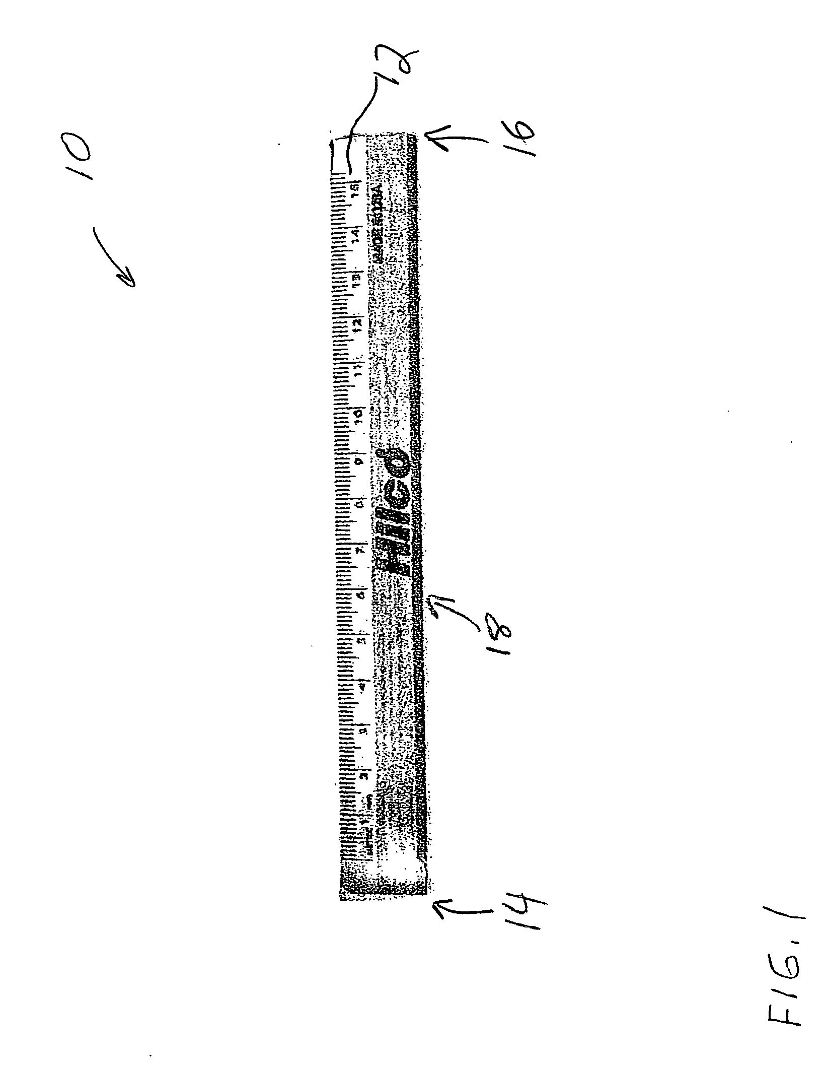
[0012] The PD ruler 20 is constructed of a rigid material, such as wood, plastic o...


PUM


Abstract

The present invention is a monocular pupillary distance (PD) ruler designed to help an eye care professional align the optical center of prescription eyewear with the patient's eye. The ruler is a planar body having an upper and a lower edge. A bridge is sized and shaped to fit upon the nose of a person being measured for eyeglasses. The bridge is located at a center point of the ruler. The ruler also includes units of measurements originating from the center point and measuring out from either side of the center point. The ruler may include a handhold extending from an end of the ruler. The handhold may be rotatable for ease of storage.

Description

FIELD OF THE INVENTION [0001] This invention relates to optical measuring devices. Specifically, the present invention relates to a monocular pupillary distance (PD) ruler for use in fitting prescription eye glasses. DESCRIPTION OF THE RELATED ART [0002] One of the most basic and important tools for the optician is the PD (pupillary distance) ruler. FIG. 1 is a front view of an existing PD ruler 10. The ruler is normally 150 millimeters long with graduated millimeters markings. A millimeter is the unit of measurement used in the optical field. The PD ruler can be used for measuring frame dimensions, as well as for measuring pupillary distance. Some PD rulers are made of plastic, while others are made of metal or wood. [0003] The person's pupillary distance must be obtained to align the optical center of prescription glasses with the person's eye. The monocular PD measurement is the distance from the centerline of the nose to the center of each pupil. The PD measurement is always imp...

Claims


Application Information

Patent Timeline
IPC IPC(8): A61B5/103
CPCA61B3/111
Inventor DUMAIS, DAVID G.
Owner DUMAIS DAVID G
Why Eureka
Try Eureka