Image pickup apparatus and method for controlling the same
a technology of image pickup and apparatus, which is applied in the direction of exposure control, instruments, television systems, etc., can solve the problem of too bright ligh
- Summary
- Abstract
- Description
- Claims
- Application Information
AI Technical Summary
Benefits of technology
Problems solved by technology
Method used
Image
Examples
first embodiment
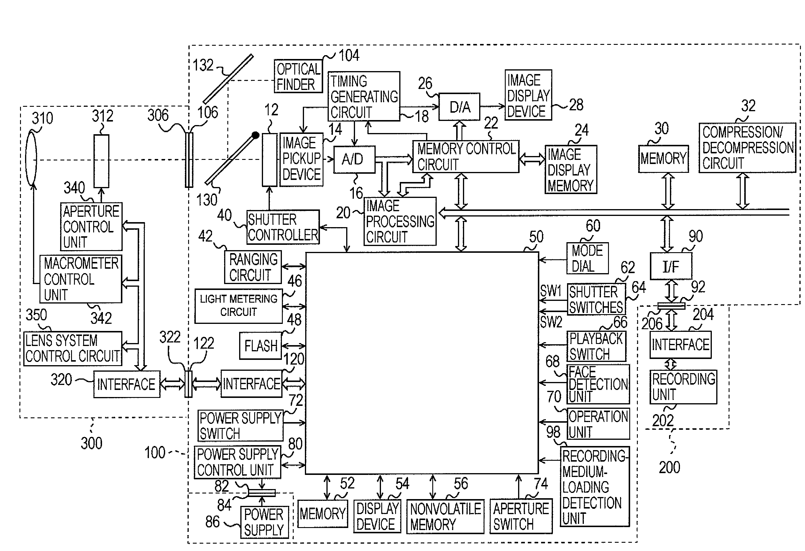
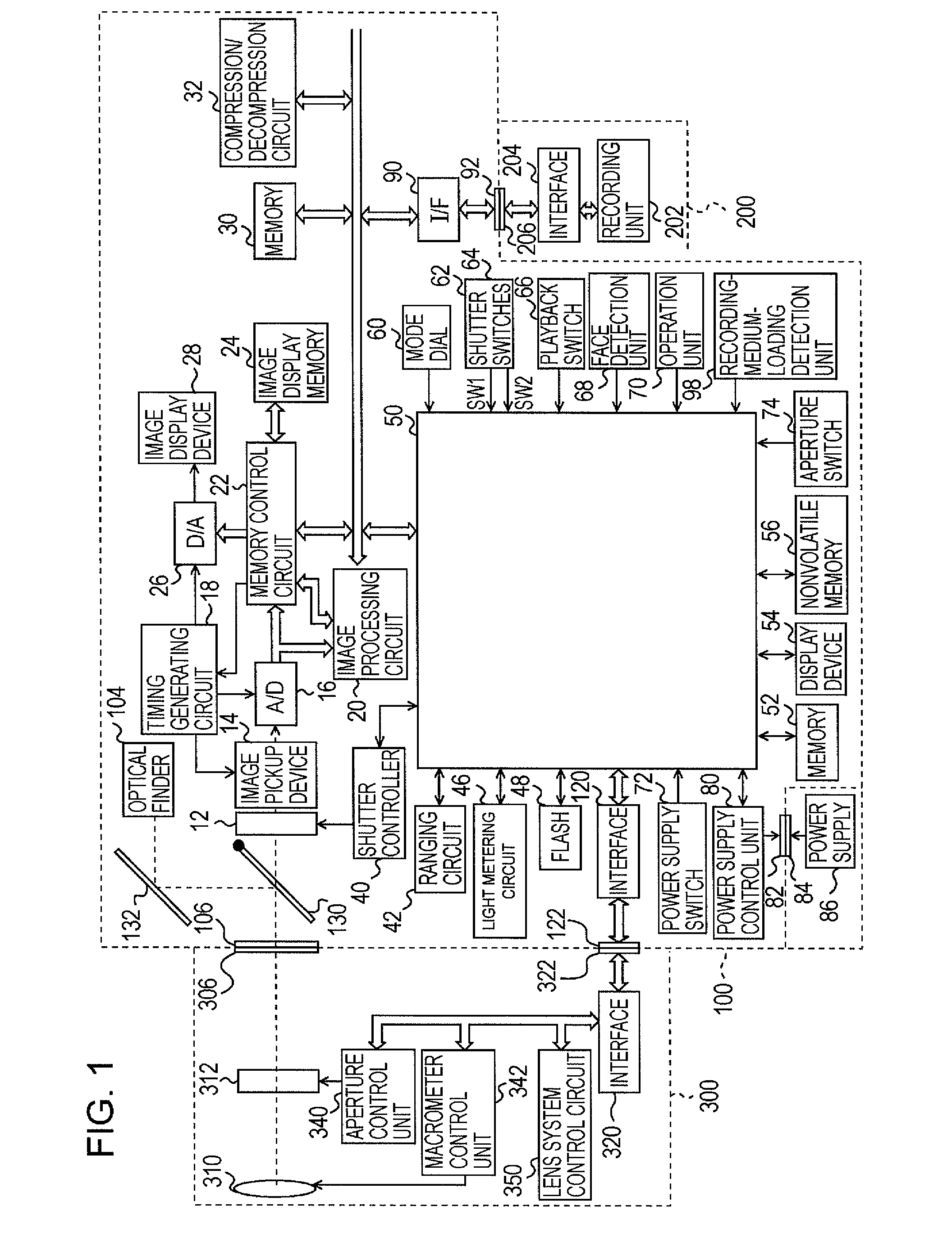
[0027]FIG. 1 is a block diagram showing the configuration of a digital single-lens reflex camera 100 as an image pickup apparatus according to a first embodiment of the present invention.
[0028]A shutter 12 controls exposure to an image pickup device 14. The image pickup device 14 converts an optical image into an electric signal. Rays of light incident on a lens 310 of a lens unit 300 form an optical image on the image pickup device 14 in a single-lens reflex system after being conducted through an aperture 312, lens mounts 306 and 106, a mirror 130, and the shutter 12.
[0029]An analog-to-digital converter 16 converts an analog signal output from the image pickup device 14 into a digital signal. A timing generating circuit 18 supplies clock and control signals to the image pickup device 14, the analog-to-digital converter 16, and a digital-to-analog converter 26. The timing generating circuit 18 is controlled by a memory control circuit 22 and a system control circuit 50.
[0030]An ima...
second embodiment
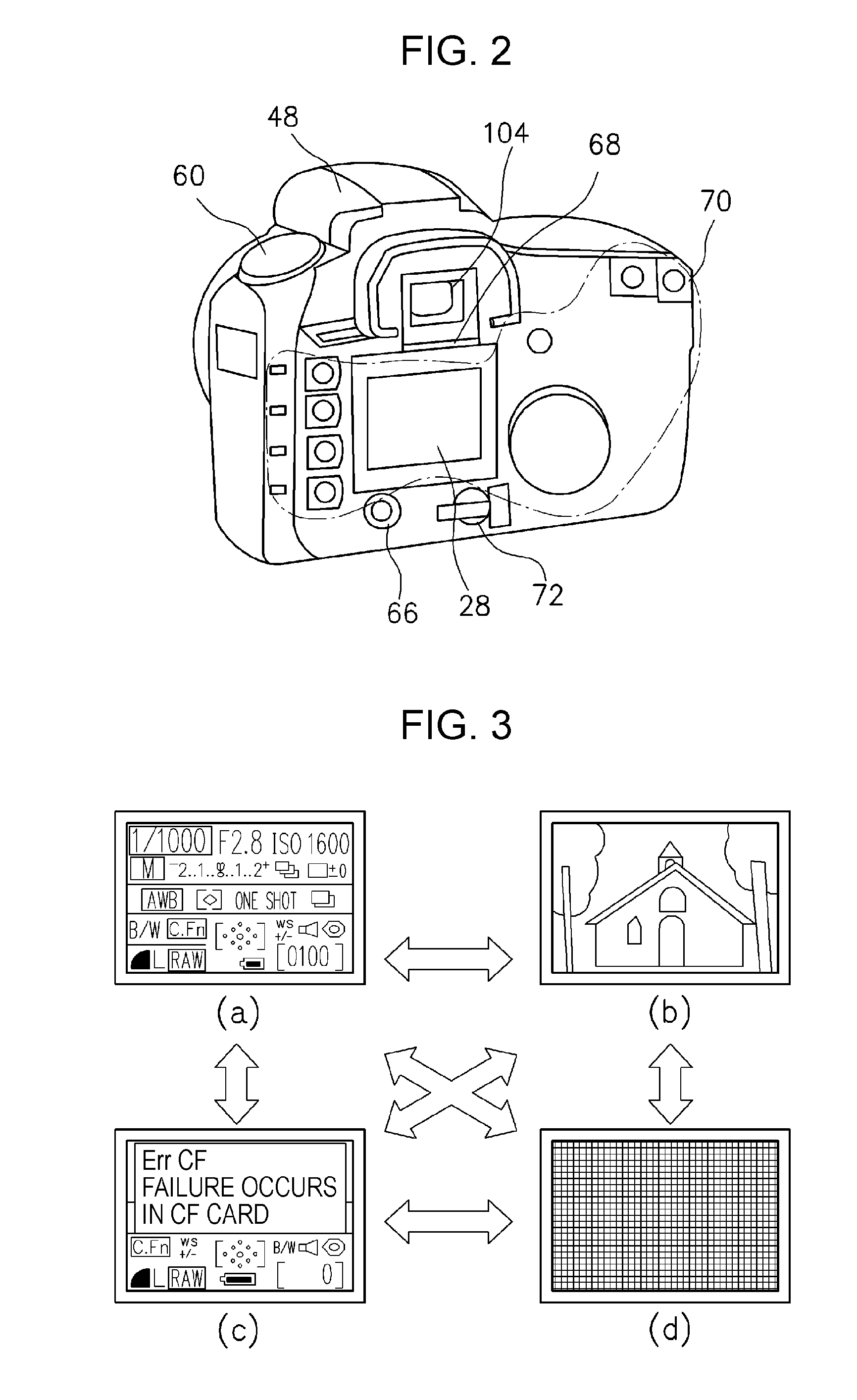
[0074]In a second embodiment of the present invention, while the alert indication of imaging prohibition is being displayed on the image display device 28, even if face detection is performed, the digital single-lens reflex camera 100 can alter a display manner of the alert indication as well as not stopping display of the alert indication. The configuration of the digital single-lens reflex camera 100 according to the second embodiment is similar to that described in the first embodiment. Accordingly, differences from the first embodiment are mainly described below.
[0075]FIG. 5 is a flowchart illustrating a control operation of the image display device 28 of the digital single-lens reflex camera 100 according to the second embodiment. After the image display device 28 initiates displaying, as content, an image or camera-state information (step S501), in step S502, a timer is activated to initiate timer counting in order to determine timing for stopping display of the content and to...
third embodiment
[0081]In a third embodiment of the present invention, while the alert indication of imaging prohibition is being displayed on the image display device 28, even if face detection is performed, the digital single-lens reflex camera 100 can alter a display manner of the alert indication as well as not turning off the alert indication. The configuration of the digital single-lens reflex camera 100 according to the third embodiment is similar to that described in the first embodiment. Accordingly, differences from the first embodiment are mainly described below.
[0082]FIG. 6 is a flowchart illustrating a control operation of the image display device 28 of the digital single-lens reflex camera 100 according to the third embodiment. After the image display device 28 initiates displaying, as content, an image or camera-state information (step S601), in step S502, a timer is activated to initiate timer counting in order to determine timing for stopping display of the content and to periodical...
PUM
 Abstract
Description
Claims
Application Information
 - R&D
- Intellectual Property
- Life Sciences
- Materials
- Tech Scout
- Unparalleled Data Quality
- Higher Quality Content
- 60% Fewer Hallucinations
Browse by: Latest US Patents, China's latest patents, Technical Efficacy Thesaurus, Application Domain, Technology Topic, Popular Technical Reports.
© 2025 PatSnap. All rights reserved.Legal|Privacy policy|Modern Slavery Act Transparency Statement|Sitemap|About US| Contact US: help@patsnap.com


