Clear view cannula

a cannula and clear view technology, applied in the field of cannulas, can solve the problems of lack of lateral support and limited use of this type of cannula, and achieve the effect of facilitating relative movemen

Inactive Publication Date: 2007-07-12
LYON THOMAS R
View PDF18 Cites 41 Cited by
  • Summary
  • Abstract
  • Description
  • Claims
  • Application Information

AI Technical Summary

Benefits of technology

[0007] A clear view cannula for use by a single hand in arthroscopic surgical operations is described that comprises a first tube that includes a distal end portion and a proximal end portion that define a central longitudinal axis. The first tube has a wall that defines an aperture aligned with the longitudinal axis and the proximal end portion includes a handle. A second tube includes a distal end portion and a proximal end portion. The second tube is positioned external to and adjoins the first tube, the second tube has a wall that defines an aperture aligned with the longitudinal axis. The distal end portions of the tubes are connected. A shield structure of the cannula includes a plurality of shield members positioned on the distal end portion of one of the tubes. The tube that includes the shield structure is longitudinally movable relative to the adjoined tube. A tapered tip is positioned on the distal end portion of one of the tubes and a shoulder is positioned on the second tube to facilitate the relative movement between the tubes. A counter-pressure ring is movably connected to the second tube and the second tube includes engagement means to secure the counter-pressure ring in position along the longitudinal axis. The counter-pressure ring provides an indication of the applied counter-pressure. A first position of the cannula includes the tube that has the shield members and the adjoined tube engaged by a first detent and a second position includes the tubes engaged by a second detent. The cannula is movable between the first and second positions by a single hand. In the second position the tube with the shield structure is repositioned distally relative to the adjoined tube along the longitudinal axis, the shield structure is deployed and the counter-pressure ring is at least is in direct contact with the skin of a patient.

Problems solved by technology

The use of this type of cannula may be limited by the surgeon's inability to determine the exact positional relationship of the tubes of the cannula during the surgical procedure.
An additional problem is that the cannulas lack the lateral support necessary to be free standing and therefore often need to be manually supported at a desired angular position relative to the patient's body during the surgical procedure.

Method used


Image

  • Clear view cannula
  • Clear view cannula
  • Clear view cannula

Examples


Embodiment Construction

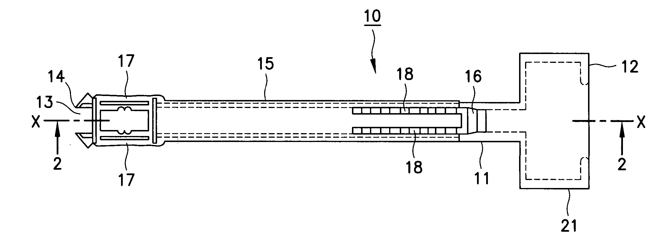
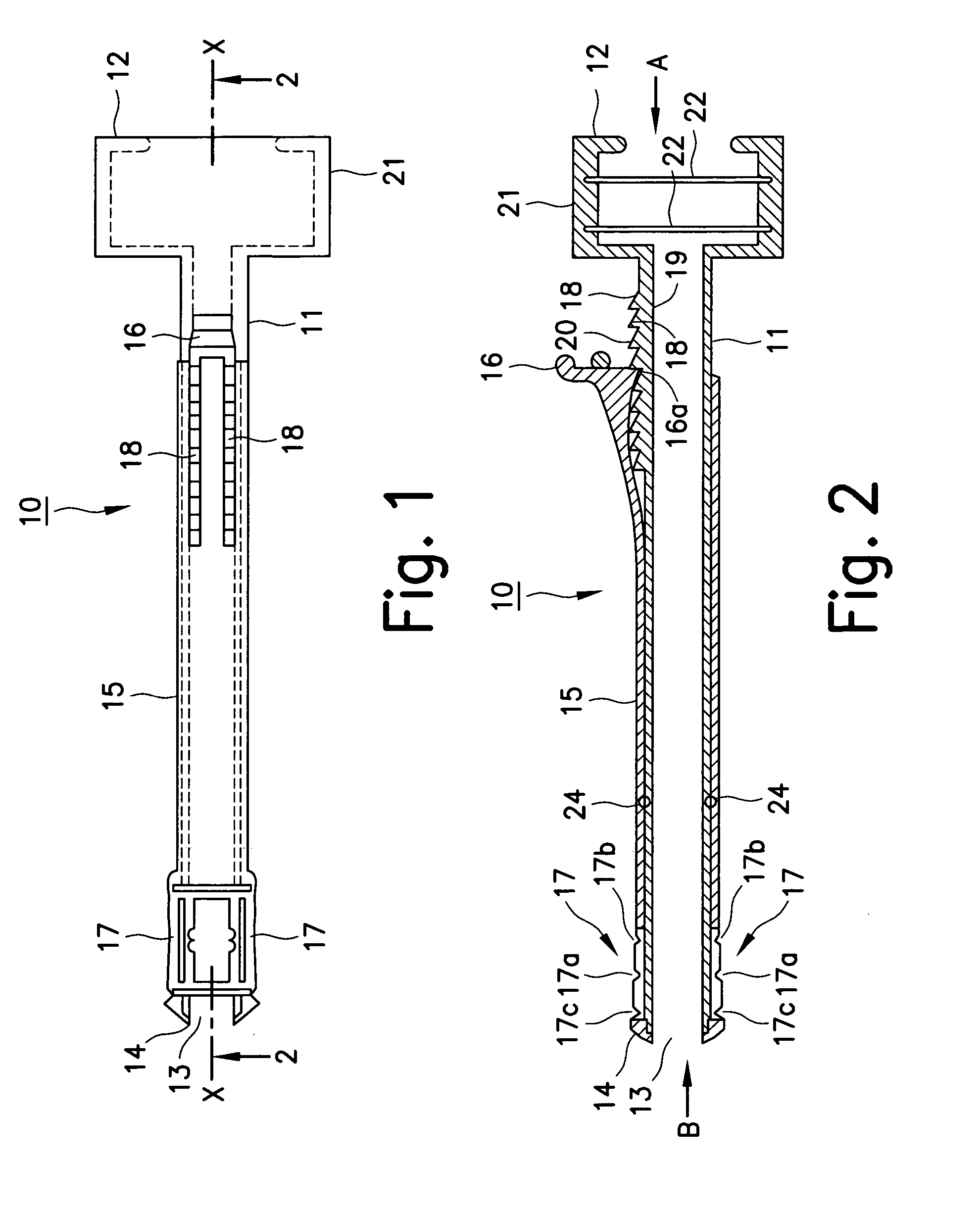
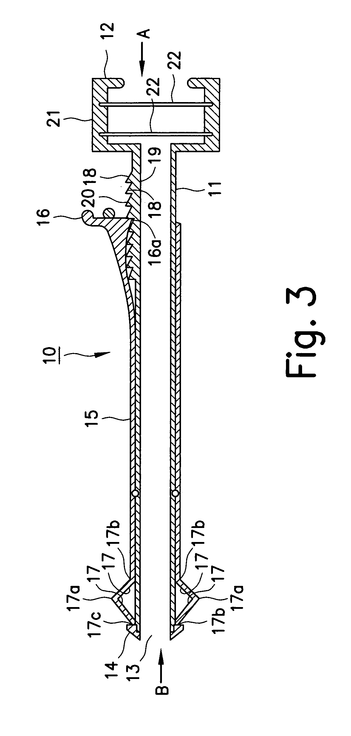
[0026] Referring to FIG. 1, a clear view cannula 10 includes a first tubular cannula body 11 that has a proximal end portion 12 and a distal end portion 13 that define a passageway that has a central longitudinal axis-X. Cannula 10 is shown in a first position for penetration through a body wall and into a portion of a body such as a joint and / or an anatomical cavity. Proximal end portion 12 includes a handle 21.

[0027] A second tube 15 is concentrically mounted and slidably secured with cannula body 11 in an adjoined close fitting relationship. Second tube or cylindrical sleeve 15 has a proximal end that includes a raised shoulder 16 for the positioning of second tube 15 relative to first tube 11. Shoulder 16 preferably extends radially from the vicinity of proximal end portion 12 in the first position of cannula 10. The distal end portion of second tube 15 is preferably connected to distal end portion 13 by a snap-fit detent, but the tubes can be connected by any conventional mean...


PUM


Abstract

A clear view cannula is described that includes a first tube, a second tube and a counter-pressure ring. The tubes are concentric, adjoined and define a longitudinally aligned aperture. The cannula has a first position for penetration or removal from a patient and a second position in which a shield structure is deployed within the patient. The ring provides a counter-pressure force that opposes the force applied by the shield structure in the second position and stabilizes the angular position of the cannula in the body of the patient. Detents in the tubes define the first position and the second position of the cannula and limit the travel between the tubes.

Description

FIELD OF THE INVENTION [0001] The present invention relates to cannulas and more specifically to cannulas used in arthroscopic minimally invasive surgery. BACKGROUND OF THE INVENTION [0002] Cannulas are surgical instruments that are used in minimally invasive surgery to introduce auxiliary surgical instruments into a body of a patient. Many cannulas have specialized structures that can expand after penetration into a body cavity. The expandable portion provides functions such as anchoring the cannula within the body and enhancing visibility into the patient. [0003] The control of the cannula during and after the initial penetration is an important part of any surgical procedure. The deployment of the expandable portion is frequently performed by manually forcing an outer cannula distally relative to an inner cannula. One such application is U.S. Pat. No. 6,632,197 to Lyon and is incorporated herein by reference and made a part of this disclosure. The use of this type of cannula may ...

Claims


Application Information

Patent Timeline
Patent Type & Authority Applications(United States)
IPC IPC(8): A61M29/00
CPCA61B17/3421A61B2017/3484A61B2017/3492A61M25/04A61B2019/465A61B2019/4857A61B2019/464A61B2090/064A61B2090/065A61B2090/0811
Inventor LYON, THOMAS R.
Owner LYON THOMAS R
Why Eureka
Try Eureka