
Apparatus and method for replacing a cardiac valve

a technology for replacing a cardiac valve and an apparatus, which is applied in the field of prosthetic cardiac devices, can solve the problems of structural degeneration, significant mortality and morbidity, and pose formidable technical challenges

Inactive Publication Date: 2007-07-12
THE CLEVELAND CLINIC FOUND
View PDF10 Cites 428 Cited by
  • Summary
  • Abstract
  • Description
  • Claims
  • Application Information

AI Technical Summary

Benefits of technology

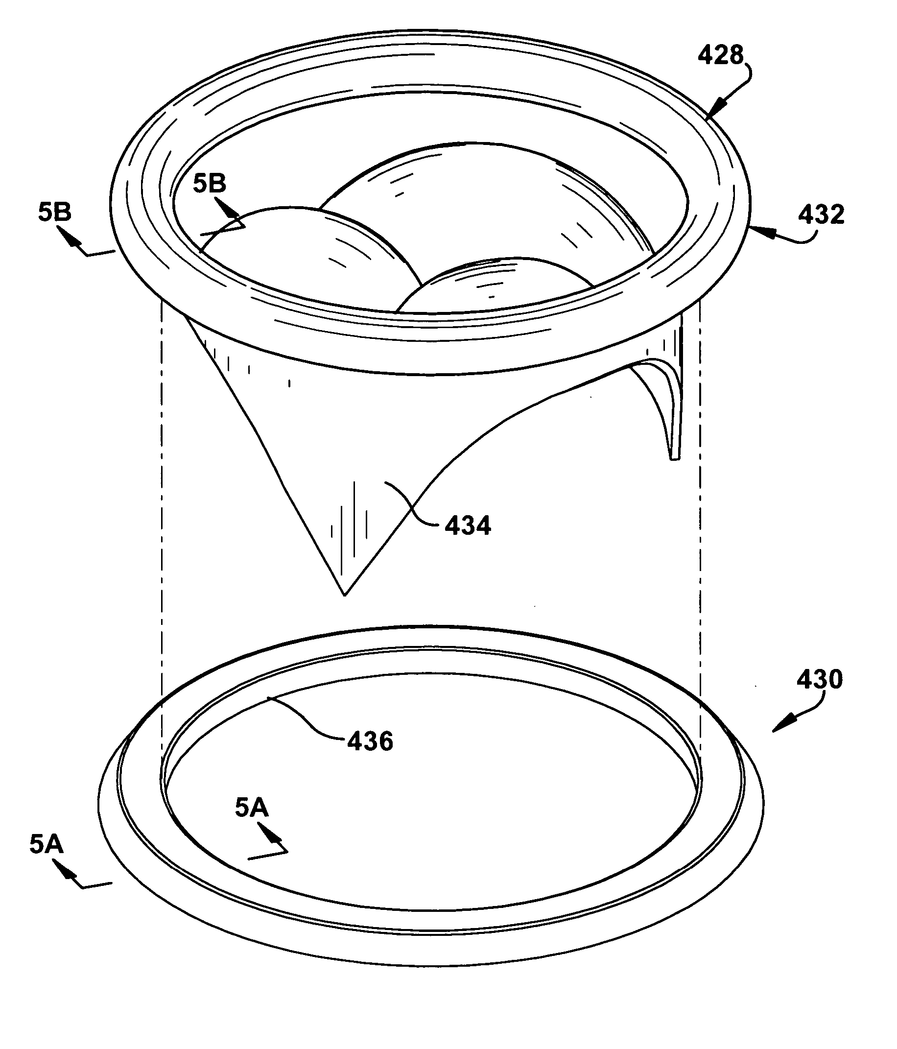
The present invention describes an apparatus and method for replacing a cardiac valve. The apparatus includes two magnetic rings that are sealingly attached together using magnets. A prosthetic cardiac valve is secured within the second ring assembly. The method involves removing the native cardiac valve and securing a first magnetic ring to the valve annulus. A second magnetic ring with the prosthetic cardiac valve is then moved into magnetic engagement with the first ring to position the valve in a predetermined relationship within the valve annulus. The technical effect of this invention is to provide a safer and less invasive method for replacing a cardiac valve.

Problems solved by technology

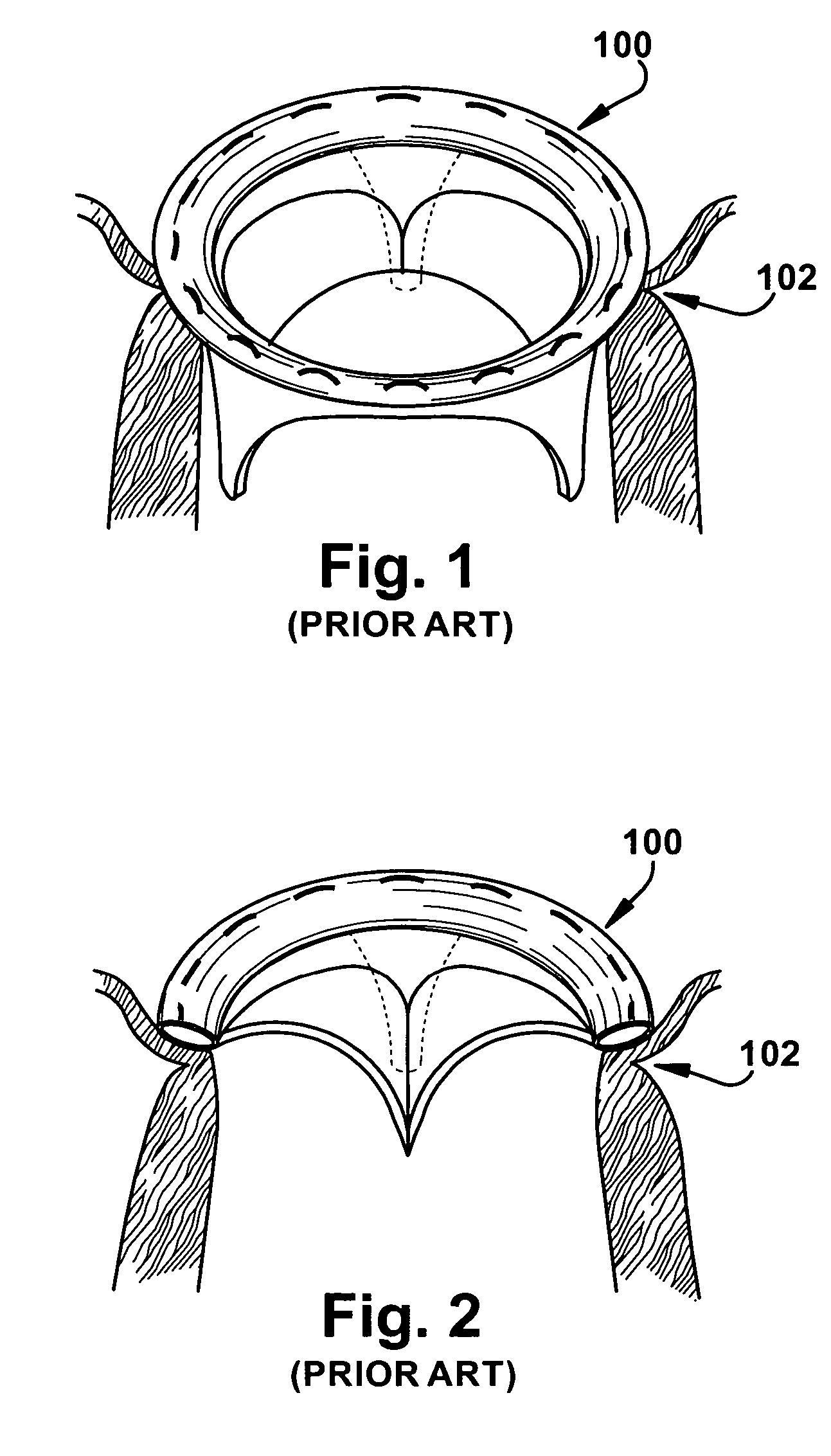
Bioprosthetic valves, such as that shown in FIGS. 1 and 2, are typically made of biological material, such as bovine pericardial tissue, and are particularly vulnerable to structural degeneration.
Reoperations for bioprosthetic cardiac valve failure are associated with significant mortality and morbidity, and can pose formidable technical challenges.
Mitral valve reoperations can also result in damage to the left circumflex coronary artery during removal of the degenerated bioprosthesis and insertion of a new bioprosthesis.
Further, with removal and replacement of either the mitral or aortic valve, late perivalvular leaks may also develop.

Method used


Image

  • Apparatus and method for replacing a cardiac valve
  • Apparatus and method for replacing a cardiac valve
  • Apparatus and method for replacing a cardiac valve

Examples


Embodiment Construction

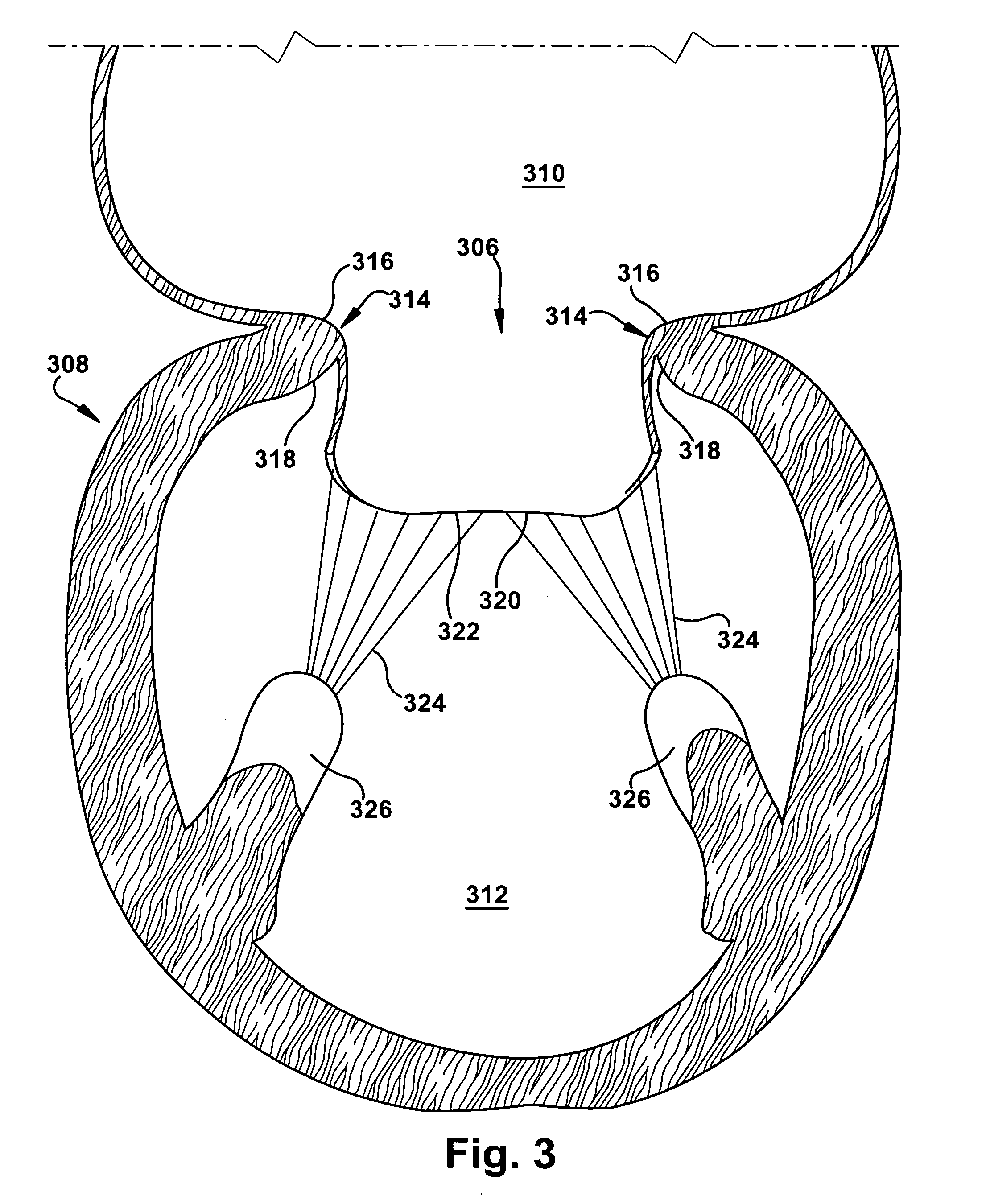
[0026]FIG. 3 depicts the positioning of the native mitral valve 306 within the heart 308. The mitral valve 306 is located between the left atrium 310 and the left ventricle 312, and functions to prevent backflow of blood from the left ventricle into the left atrium during left ventricular contraction. The mitral valve 306 has a D-shaped annulus 314 with superior and inferior aspects 316 and 318, respectively, which define the opening between the left atrium 310 and the left ventricle 312. The mitral valve 306 is formed by two leaflets; namely, the anterior leaflet 320 and the posterior leaflet 322. The anterior leaflet 320 extends along the generally planar base of the D-shaped annulus 314, while the posterior leaflet 322 extends arcuately around the curved portion of the D-shaped annulus of the mitral valve 306. Chordae tendineae 324 extend between the free edges of both leaflets 320 and 322 and the papillary muscles 326 in the left ventricle 312. The leaflets 320 and 322 are excis...


PUM


Abstract

An apparatus for replacing a cardiac valve includes a first ring assembly and a second ring assembly. The first ring assembly includes a first magnetic member. The second ring assembly includes a second magnetic member and is magnetically attachable to the first magnetic member to sealingly attach the first and second ring assemblies together. A prosthetic cardiac valve is secured within the second ring assembly. A method for replacing a cardiac valve is also described.

Description

RELATED PATENT APPLICATION [0001] This application claims priority to the filing date of U.S. Provisional Application No. 60 / 696,934, filed Jul. 6, 2005.TECHNICAL FIELD [0002] The present invention relates generally to prosthetic cardiac devices, and more particularly to an apparatus and method for replacing a cardiac valve. BACKGROUND OF THE INVENTION [0003] Implantable heart valve prostheses have been used to replace various diseased or damaged natural aortic valves, mitral valves, pulmonary valves and tricuspid valves of the heart. The aortic and mitral valves are most frequently replaced due to heart disease, congenital defects and / or injury. Diseased or malfunctioning heart valves are typically replaced with either mechanical or bioprosthetic heart valve prostheses. A typical known bioprosthetic valve 100 is depicted in place within a valve annulus 102 in FIGS. 1 and 2. Bioprosthetic valves, such as that shown in FIGS. 1 and 2, are typically made of biological material, such as...

Claims


Application Information

Patent Timeline
Patent Type & Authority Applications(United States)
IPC IPC(8): A61F2/24
CPCA61F2/2403A61F2/2409A61F2/2412A61F2250/0063A61F2002/9528A61F2210/009A61F2/2427A61F2250/006
Inventor FUKAMACHI, KIYOTAKADESSOFFY, RAYMOND
Owner THE CLEVELAND CLINIC FOUND
Learn More