Intervertebral spacer and insertion tool

a technology of intervertebral spacers and inserters, which is applied in the field of improved implants and implant inserters, can solve the problems of affecting the design of such implants, affecting the use of certain desirable materials, and affecting the quality of implant designs

Active Publication Date: 2007-07-12
WARSAW ORTHOPEDIC INC
View PDF74 Cites 87 Cited by
  • Summary
  • Abstract
  • Description
  • Claims
  • Application Information

AI Technical Summary

Problems solved by technology

A number of medical conditions such as compression of spinal cord nerve roots, degenerative disc disease, herniated nucleus pulposis, spinal stenosis and sp...

Method used


Image

  • Intervertebral spacer and insertion tool
  • Intervertebral spacer and insertion tool
  • Intervertebral spacer and insertion tool

Examples


Embodiment Construction

[0036]For the purposes of promoting an understanding of the principles of the present invention, reference will now be made to the embodiments illustrated in the drawings, and specific language will be used to describe the same. It will nevertheless be understood that no limitation of the scope of the invention is intended thereby. Any alterations and further modifications in the described devices, instruments, methods and any further application of the principles of the invention as described herein are contemplated as would normally occur to one skilled in the art to which the invention relates.

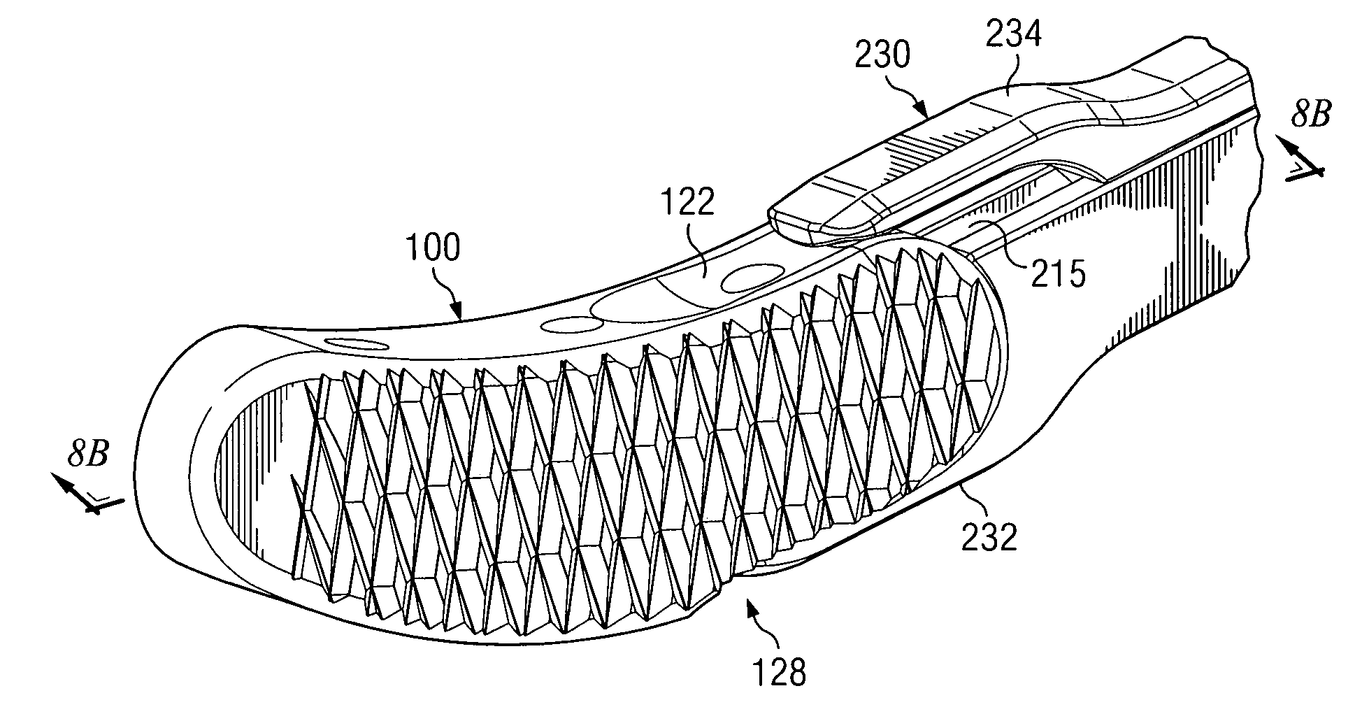
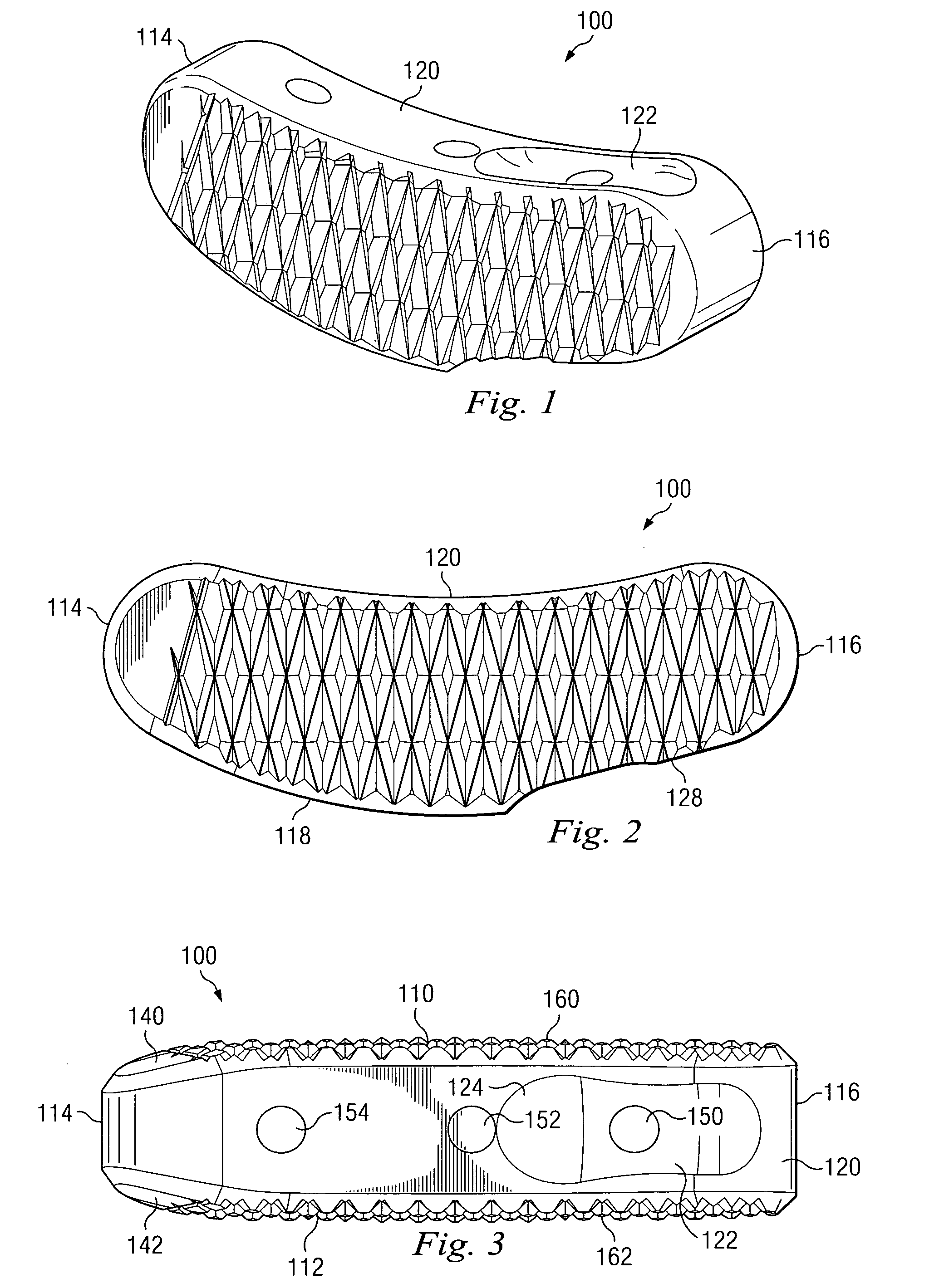
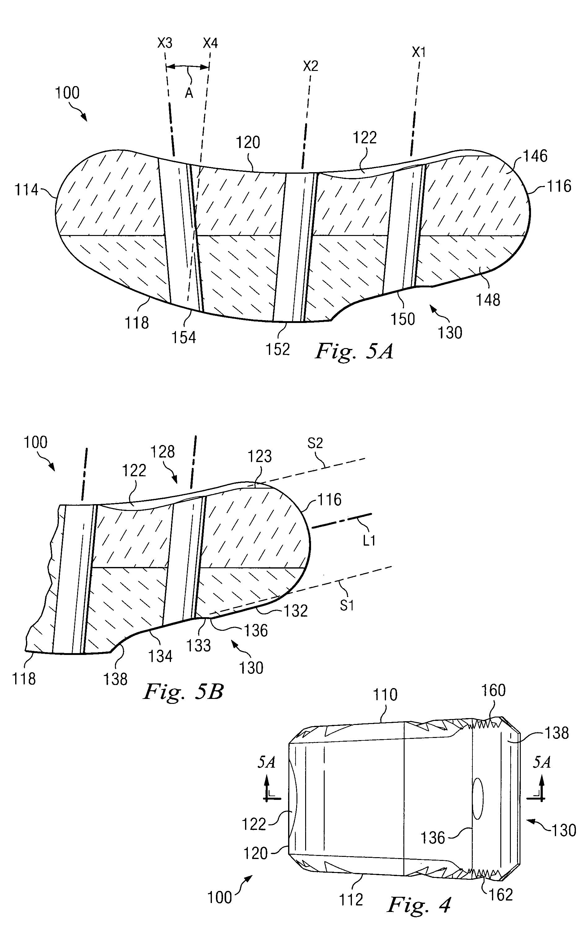
[0037]Referring now to FIG. 1, there is shown a perspective view of an implant according to one aspect of the present invention. As shown more fully in FIGS. 1-5B, implant 100 includes an upper surface 110 and an opposing lower surface 112; each configured for contact with and / or placement in close approximation to the bone of adjacent upper and lower vertebrae, respectively. Implant 100 in...


PUM

PropertyMeasurementUnit
Angleaaaaaaaaaa
Angleaaaaaaaaaa
Angleaaaaaaaaaa

Abstract

An implant for placing in the spine is disclosed. The implant has a tool engaging surface on its trailing end configured for intimate engagement with an insertion tool. The insertion tool configuration is particularly suited for implants made of brittle materials including bone and bone substitutes. Also disclosed is an insertion tool having a gripping end adapted for intimate engagement with an implant. In one embodiment, the insertion tool is operable by axial movement of one gripping arm with respect to the other.

Description

FIELD OF THE INVENTION[0001]The present invention is directed to improved implants, implant inserters and methods of their use. More particularly, the present invention is directed to spinal implants and instrumentation for use in performing interbody spine stabilizations.BACKGROUND OF THE INVENTION[0002]The present invention relates to interbody stabilization procedures of vertebrae in the spine, including fusions and disc space height restorations. A number of medical conditions such as compression of spinal cord nerve roots, degenerative disc disease, herniated nucleus pulposis, spinal stenosis and spondylolisthesis can cause severe low back pain. Restoration of the space between adjacent vertebrae and / or removal of the anatomical structure pushing against the spinal cord or exiting nerve roots is known to alleviate patient suffering. It is often desirable to stabilize the restored disc space by placing a spacer within the intervertebral space. Some intervertebral implants rest o...

Claims


Application Information

Patent Timeline
IPC IPC(8): A61F2/44
CPCA61F2/28A61F2310/00359A61F2/4465A61F2/4611A61F2002/30062A61F2002/30112A61F2002/30131A61F2002/30387A61F2002/30398A61F2002/30436A61F2002/30476A61F2002/30492A61F2002/30538A61F2002/30795A61F2002/30805A61F2002/30836A61F2002/30841A61F2002/30904A61F2002/30975A61F2002/4622A61F2002/4627A61F2002/4628A61F2210/0004A61F2220/0025A61F2220/0041A61F2230/0004A61F2230/0013A61F2250/0006A61F2310/00179A61F2310/00293A61F2310/00341A61F2/30771A61F2002/30433
Inventor DERIDDER, STEVEN D.SCHWENDER, JAMES D.SHAFFREY, CHRISTOPHER I.SIMONTON, T. ANDREW
Owner WARSAW ORTHOPEDIC INC
Why Eureka
Try Eureka