Orthopaedic Implants and Prostheses

Inactive Publication Date: 2009-08-20
THALGOTT JOHN +1
View PDF0 Cites 378 Cited by
  • Summary
  • Abstract
  • Description
  • Claims
  • Application Information

AI Technical Summary

Benefits of technology

[0018]It is an advantage that the practitioner can select an appropriate size of spacer and appropriate sizes of plates from the kit of parts to suit the particular size and shape of the space into which the implant or prosthesis is to

Problems solved by technology

The cause of this pain is often difficult to diagnose.
Bones and related structural body parts, for example spine and/or vertebrae and/or intervertebral discs, may become crushed or damaged as a result of trauma/injury, or damaged by disease (e.g. by tumour, auto-immune disease), or damaged as a result of degeneration through an aging process.
While there has been an evolution of the shape of implants and some attempts to provide modular implants, the inventors have recognized that such changes have been relatively minor and have not fully contemplated cooperation between optimizing the surgical result and improving efficiency and safety of the operative procedure.
Another problem that the inventors have recognized with conventional implants is an absence of variability in the vector that the bone fixator (screw) may be directed for securement to the vertebral bodies relat

Method used


Image

  • Orthopaedic Implants and Prostheses
  • Orthopaedic Implants and Prostheses
  • Orthopaedic Implants and Prostheses

Examples


example 1

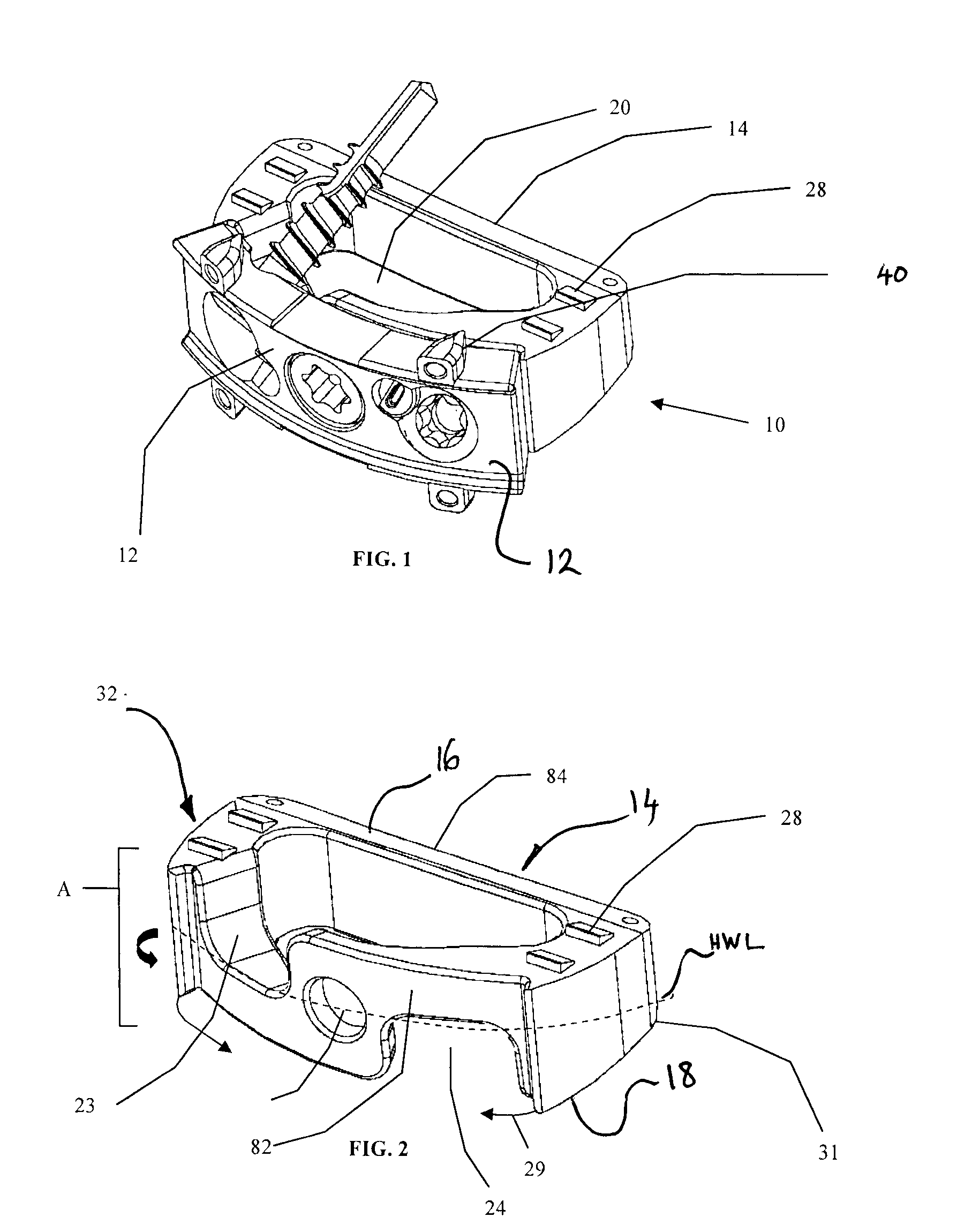
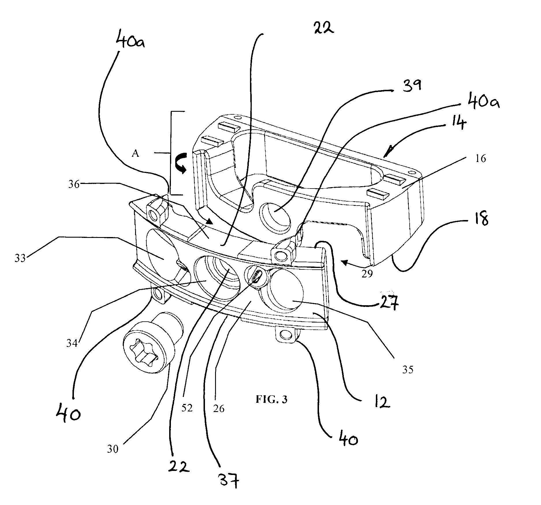
[0047]With reference to FIGS. 1-8 a spinal implant embodiment will now be described. FIG. 1 shows an anterior perspective view of a spinal implant 10 embodiment that includes a plate component 12 and a spacer component 14. The spacer component 14 comprises a cavity 20 defined therein for disposing a bone ingrowth material. The plate component 12 comprises a keel 40 having an apex that serves to penetrate the bone surface of a vertebral body. It should be noted that the plate 12 may be utilized with or without the spacer component 14.

[0048]FIG. 2 shows a perspective view of the spacer component 14. The spacer component 14 has an anterior body portion 82 and a posterior body portion 84. The spacer component 14 also has a lateral end 31 and a lateral end 32. The spacer component has a top surface 16 and a bottom surface 18 (see FIGS. 4, 5&6d) and a side perimeter surface A. The anterior body portion 82 has an anterior side 29. On the anterior side 29 of the anterior body portion 82 is ...

example 2

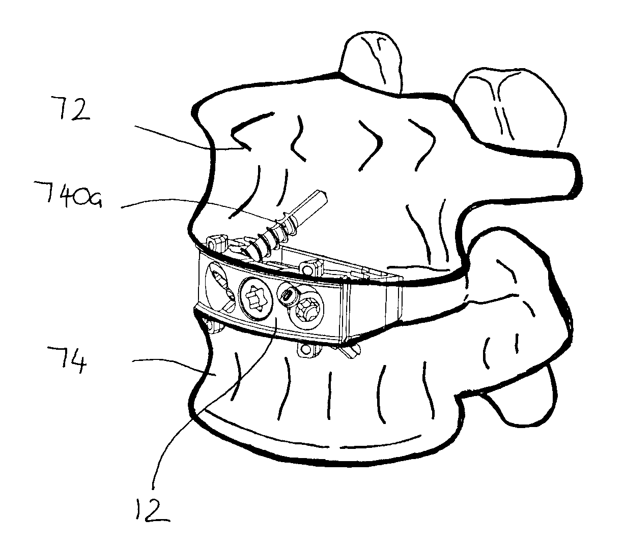
[0053]FIG. 9 shows a two-hole buttress plate 900 and FIG. 10 shows a one-hole buttress plate 1000 suitable for securing an implant within a vertebral cavity and particularly suitable for adding a further degree of security of fixing to the implant embodiments shown herein. The buttress plates 900 and 1000 are designed to attach to a vertebral body that is either superior to an intervertebral space into which an implant has been positioned such as that shown in FIGS. 11 and 12, or inferior to the intervertebral space into which an implant is positioned, or could be more than one with one buttress plate superiorly secured and one inferiorly secured. The buttress plates 900, 1000 may be secured with any suitable fastener, but are advantageously secured with the screws 740 such as that described above in relation to FIGS. 4 and 5, that are passed through either two holes for plate 900 or one hole for plate 1000 (holes hidden underneath head of screw). Figures. 9 and 10 also shows shifta...

example 3

[0055]Turning now to FIG. 13, a side perspective view of an implant 1300 is shown, which is particular useful for a lateral surgical approach. The implant 1300 comprises a spacer component 1314 and a plate component 1312. The spacer component 1314 comprises an anterior body portion 1382 and a posterior body component 1384. The plate component 1312 comprises cam locks 1351, 1352 which assist in preventing “backing out” of screws passing through channels in the plate component 1312, which is discussed in further detail below.

[0056]FIG. 14 shows a side perspective view of the spacer component 1314. The spacer component 1314 has a first lateral end 1331 and a second lateral end 1332. The spacer has a side perimeter surface as depicted by the arrows. Defined in the first lateral end 1331 are a first fixator portal 1323 and a second fixator portal 1324 which open at the side surface 1329 of the first lateral end 1331. Again, the portals are open to the immediately adjacent planar upper or...


PUM


Abstract

Disclosed herein are spinal implants particularly useful in interbody fusion surgery. One embodiment pertains to a plate configured to establish desired lordosis and/or disc height that may be implanted and secured to a superior and inferior vertebral body. The plate may be interlocked with a spacer component to form a single implant. Also disclosed is an anti-backout mechanism that helps prevent fixators from backing out upon securement of the plate in the spine. Kits comprising different sizes and inclination angles of components are disclosed, which can assist the surgeon in preoperatively assembling an implant to best fit in the surgical site of the patient.

Description

FIELD OF THE INVENTION [0001]The present invention relates to orthopaedic implants and / or prostheses and instrumentation for their implantation. The invention is applicable to bone structures, particularly the cervical, thoracic and lumbar spine.GENERAL BACKGROUND [0002]Spinal fusion for the management of lumbar degenerative disc disease has been available for several decades. The results of this procedure remain under constant scrutiny and progressive development. Anterior lumbar fusion was initially introduced in the early 1920s. Fibula and iliac struts, femoral rings and dowel, as well as synthetic metallic devices have been applied as fixation implements to aid in lumbar interbody fusion. Approaches to the spine have experienced similar evolutionary changes. Prior to the 1950s most anterior lumbar approaches were extensive transperitoneal exposures (i.e. through the membrane lining the walls of the abdominal and pelvic cavities). In 1957, Southwick and Robinson introduced the r...

Claims


Application Information

Patent Timeline
IPC IPC(8): A61F2/44A61B17/04
CPCA61B17/86A61F2/30744A61F2/4465A61F2002/2817A61F2002/30405A61F2002/30426A61F2002/30517A61F2002/30593A61F2002/30604A61F2002/3079A61F2002/30884A61F2002/30904A61F2220/0025
Inventor THALGOTT, JOHNSTINSON, DAVID T.
Owner THALGOTT JOHN
Why Eureka
Try Eureka