Ceramic disc prosthesis

a technology for cervical discs and prostheses, applied in the field of cervical disc prosthesis, can solve the problems of anatomical and functional destruction of the disc and the vertebral segment, the change of various bones, and the inability to control the rotation of the disc. , to achieve the effect of optimizing post-operative imaging and superior wear properties

Active Publication Date: 2006-01-05
DEPUY SPINE INC (US)
View PDF95 Cites 376 Cited by
  • Summary
  • Abstract
  • Description
  • Claims
  • Application Information

AI Technical Summary

Benefits of technology

[0007] The present invention provides a disc prosthesis that features superior wear properties. The disc prosthesis is formed entirely or predominately of ceramic material, thus optimizing post-operative imaging. In one embodiment, the present invention provides an implantable prosthetic device for replacing spinal discs. The device includes first and second endplates each having an articulating contact surface and a bone facing surface. At least one of the first and second endplates is formed of a ceramic material. The contact surface of the first endplate has a shape complementary to the contact surface of the second end plate, such that when the endplates are in contact with each other, the contact surface of the first endplate can articulate with respect to the contact surface of the second endplate.

Problems solved by technology

Disease, advancing age, and trauma can lead to changes in various bones, discs, joints, and ligaments of the body.
It is known that an intervertebral disc can be subject to damage, such as compression, deformation, displacement, or wear, and more generally degeneration associated with the mechanical stresses that are applied thereto and that lead to anatomical and functional destruction of the disc and of the vertebral segment.
This damage to the disc alters its mechanical behavior and causes instability which can, in turn, give rise to a painful osteoarthritic reaction.
Although such prostheses makes it possible to restore an appropriate height to the intersomatic gap, the articulating mechanism of the prosthesis can be subject to high levels of friction, thus making it sensitive to wear.
While the ceramic materials reduce wear, these implants are limited by small bearing surfaces.
In addition, mounting stiff ceramic inserts into titanium endplates can generate high stresses in the ceramic material and cause disc failure.
Thick titanium endplates can also interfere with post-operative imaging, an important diagnostic tool.

Method used


Image

  • Ceramic disc prosthesis
  • Ceramic disc prosthesis
  • Ceramic disc prosthesis

Examples


Embodiment Construction

[0042] Certain exemplary embodiments will now be described to provide an overall understanding of the principles of the structure, function, manufacture, and use of the devices and methods disclosed herein. One or more examples of these embodiments are illustrated in the accompanying drawings. Those skilled in the art will understand that the devices and methods specifically described herein and illustrated in the accompanying drawings are non-limiting exemplary embodiments and that the scope of the present invention is defined solely by the claims. The features illustrated or described in connection with one exemplary embodiment may be combined with the features of other embodiments. Such modifications and variations are intended to be included within the scope of the present invention.

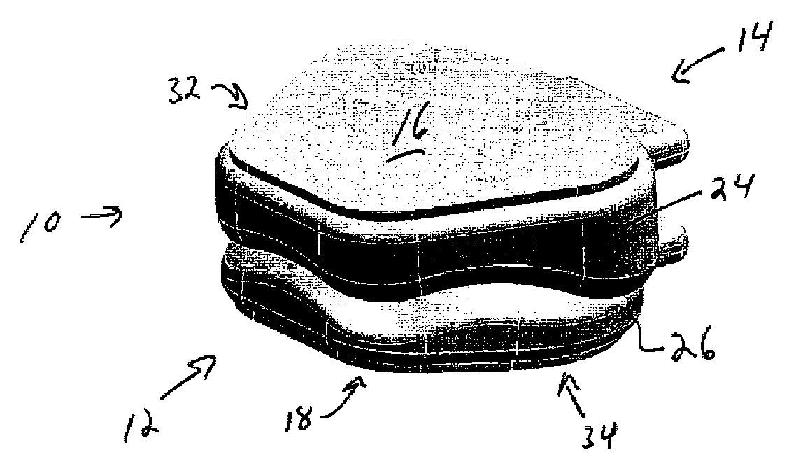
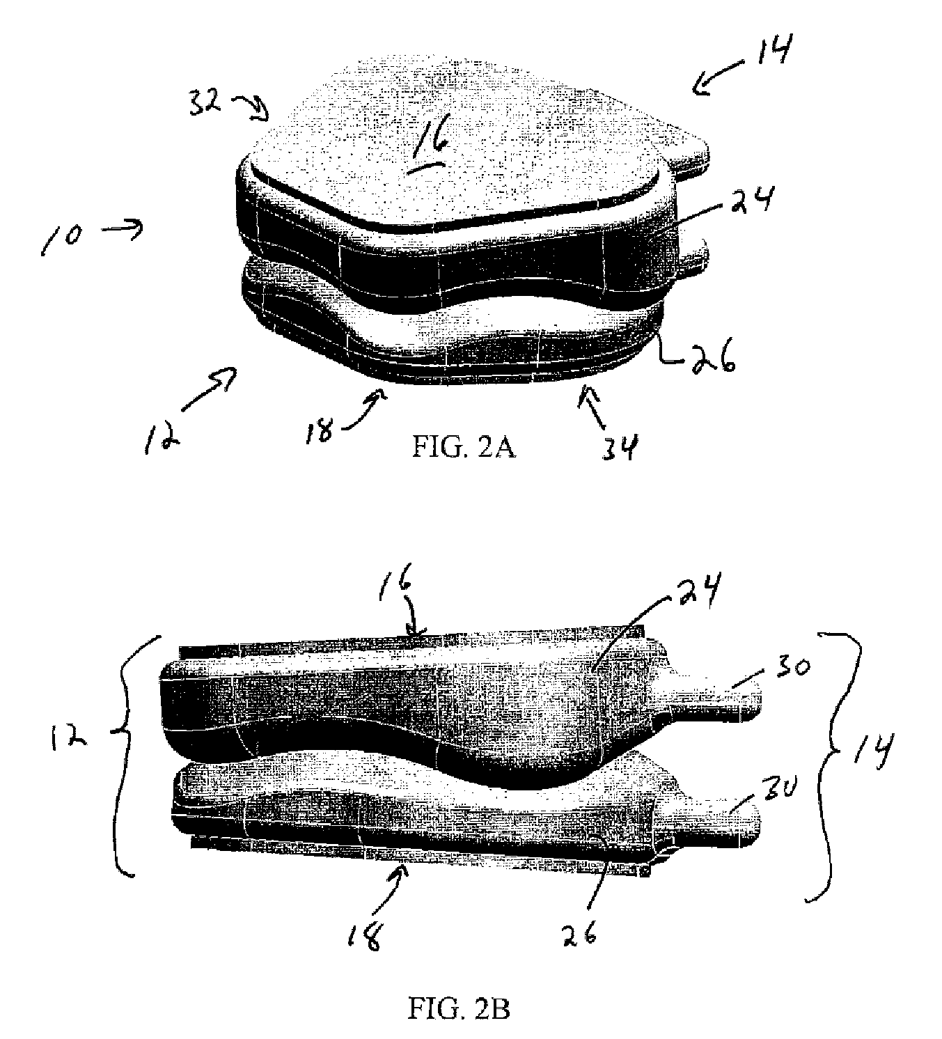
[0043] The present invention provides a prosthesis that conserves vertebral function and provides wear resistant articulation surfaces. In one aspect, superior tribological wear properties are provi...


PUM

PropertyMeasurementUnit
angleaaaaaaaaaa
angleaaaaaaaaaa
angleaaaaaaaaaa

Abstract

A prosthetic is provided for replacing a vertebral disc. The prosthesis can comprise first and second endplates formed of a ceramic material, each including an articulating contact surface and a bone facing surface. The contact surface of the first endplate can have a shape complementary to the contact surface of the second endplate, thereby facilitating articulation of the first and second endplates while in contact with one another. The device can further include at least one non-ceramic bone attachment element mated with at least one of the bone facing surfaces, such that the bone attachment element covers less than a full area of the bone facing surface.

Description

CROSS REFERENCE TO RELATED APPLICATIONS [0001] The present invention claims priority to U.S. Provisional Application Ser. No. 60 / 584,054, filed on Jun. 30, 2004 and entitled “Ceramic Artificial Disc,” which is hereby incorporated by reference in its entirety.BACKGROUND OF THE INVENTION [0002] Disease, advancing age, and trauma can lead to changes in various bones, discs, joints, and ligaments of the body. Some changes manifest themselves in the form of damage or degeneration to a spinal disc. It is known that an intervertebral disc can be subject to damage, such as compression, deformation, displacement, or wear, and more generally degeneration associated with the mechanical stresses that are applied thereto and that lead to anatomical and functional destruction of the disc and of the vertebral segment. This damage to the disc alters its mechanical behavior and causes instability which can, in turn, give rise to a painful osteoarthritic reaction. [0003] This pain can sometimes be el...

Claims


Application Information

Patent Timeline
Patent Type & Authority Applications(United States)
IPC IPC(8): A61F2/44
CPCA61F2/30767A61F2310/00796A61F2/4425A61F2/4611A61F2002/30095A61F2002/30179A61F2002/305A61F2002/30561A61F2002/30579A61F2002/30649A61F2002/30841A61F2002/30904A61F2002/443A61F2210/0023A61F2220/0025A61F2230/0058A61F2310/00017A61F2310/00023A61F2310/00203A61F2310/00239A61F2310/00407A61F2/30965A61F2002/30092
Inventor BARTISH, CHARLES M. JR.BROUSSEAU, JEFFREYFATYOL, PATRICKMCCREA, CONOR
Owner DEPUY SPINE INC (US)
Why Eureka
Try Eureka