Push-pull cap a bottle and a bottle having the push-pull cap

Inactive Publication Date: 2007-07-19
CHO YOUNG KOOK
View PDF0 Cites 9 Cited by
  • Summary
  • Abstract
  • Description
  • Claims
  • Application Information

AI Technical Summary

Benefits of technology

[0016] In another aspect, the present invention provides a bottle that can be held with one hand and having the push-pull cap, with the bottle comprising: a bottle body including a body part formed at a position below an intermediate part of the bottle body, and a waist part, a chest part and a neck part formed at a position above the intermediate part of the bottle body, wherein the chest part is bulged outwards such that the chest part can be held with an index finger, a middle finger and a ring finger of one hand, and the waist part is recessed inwards to a predetermined depth and has an angled shoulder so that a palm, an edge and a little finger of the hand are placed around the waist par, and the chest part has a predetermined size such that the chest

Problems solved by technology

However, the upper cap unit of the conventional push-pull cap is easily contaminated with polluted air or germs because it is always exposed to the atmosphere.
The upper cap unit also has a structural disadvantage in that it is easily lost.
Furthermore, it is almost impossible to keep the push-pull cap in a hygienic state for a lengthy period of time when the cap is used with a portable bottle, which may be constantly carried by a user.
However, the portable beverage bottle is problematic in that it does not have any means for allowing a user to o

Method used


Image

  • Push-pull cap a bottle and a bottle having the push-pull cap
  • Push-pull cap a bottle and a bottle having the push-pull cap
  • Push-pull cap a bottle and a bottle having the push-pull cap

Examples


Embodiment Construction

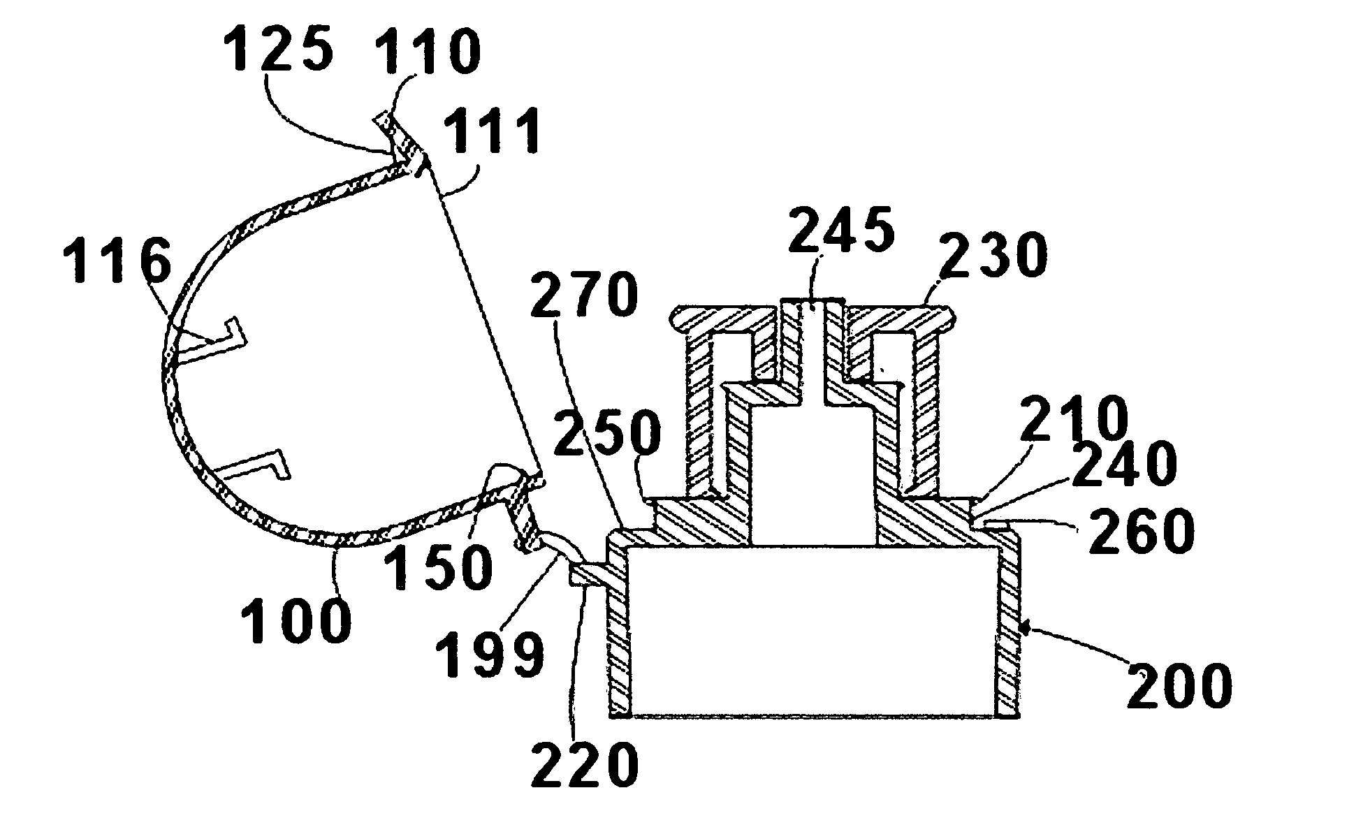
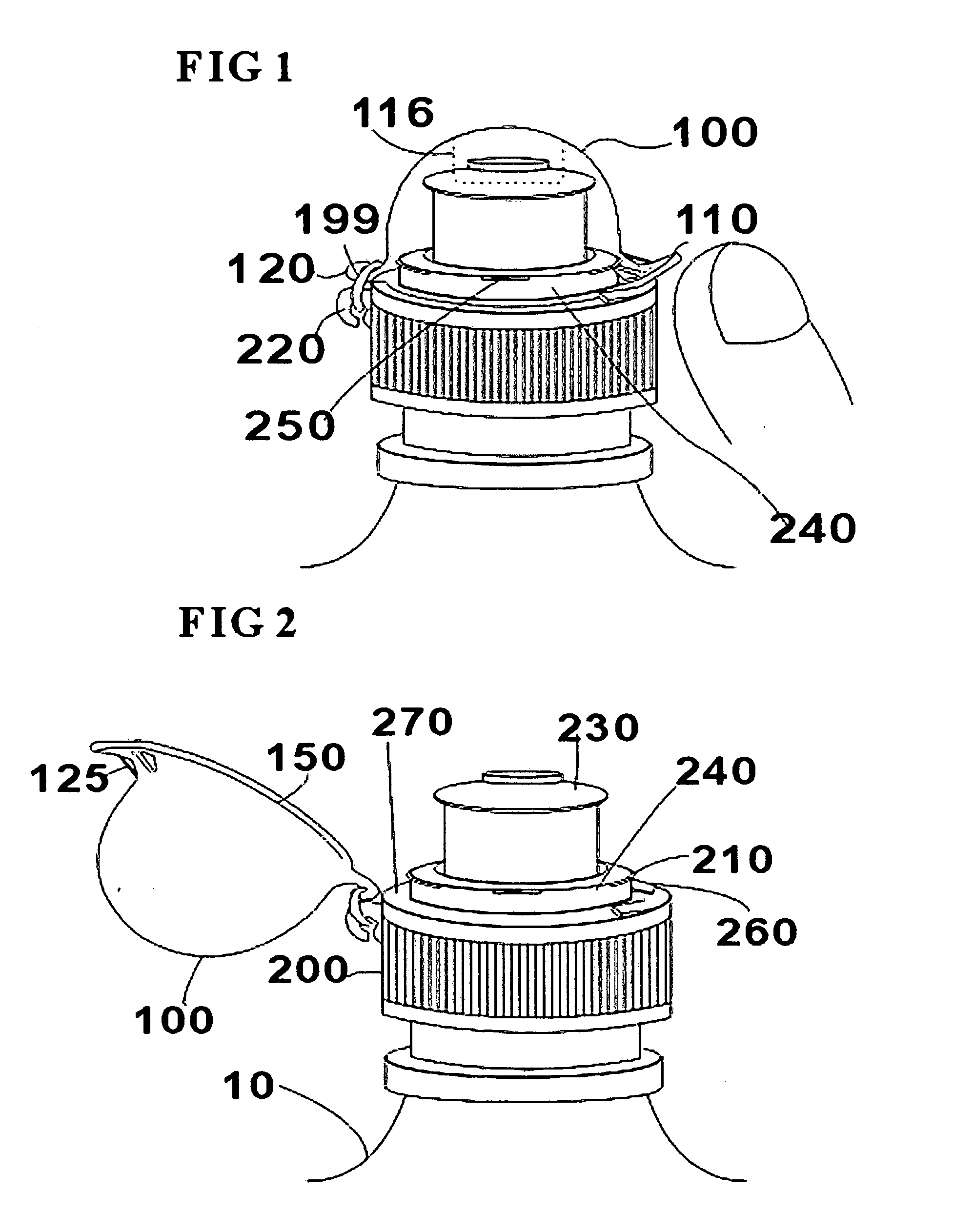
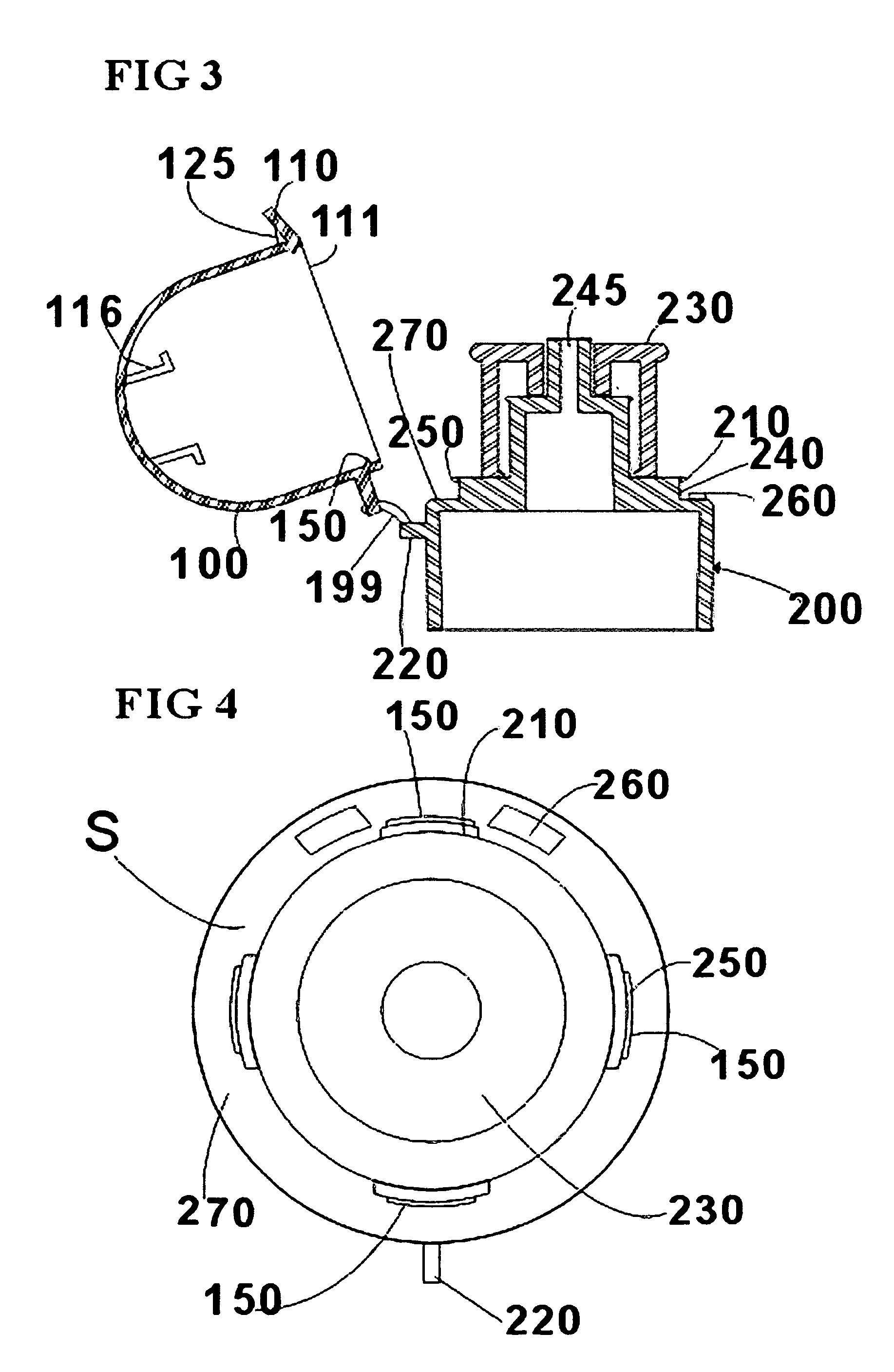
[0032] Herein below, the embodiments of the present invention will be described in detail with reference to the accompanying drawings. FIG. 1 is a perspective view of a push-pull cap according to the present invention when the cap is completely assembled. FIG. 2 is a perspective view of the push-pull cap when an upper cap unit of the push-pull cap is open. FIG. 3 is a side sectional view of the opened upper cap unit. FIG. 4 is a plan view illustrating a lower cap unit of the push-pull cap.

[0033] As shown in FIGS. 1 to 7, the push-pull cap of the present invention has an upper cap unit 100 and a lower cap unit 200 coupled thereto. The upper cap unit 100 has an appearance similar to a conventional cap, which covers a lip contact part 230, with an upper locking ring 120 formed on a side surface of the upper cap unit 100 at a predetermined position and a finger grip 110 formed on the side surface of the upper cap unit 100 at the opposite position. The lower cap unit 200 has an appearan...


PUM


Abstract

Disclosed is a push-pull cap for bottles, which is configured such that a lip contact part of the cap can be kept in a hygienic state and an upper cap unit or a protective cap unit of the push-pull cap can be easily and simply manipulated to be opened with one hand holding a bottle, and the upper cap unit can be maintained at a state of being coupled to the cap without being lost. The present invention also provides a bottle, which has the push-pull cap and is capable of being held with one hand. The push-pull cap for bottles includes: an upper cap unit and a lower cap unit, which are coupled to each other using an elastic extensible hinge connector a lifting means provided at a predetermined position on the lower cap unit corresponding to a position of a finger grip of the upper cap unit, so that the lifting means guides a lifting motion of the upper cap unit when a user rotates the upper cap unit leftwards or rightwards at a predetermined angle using a finger of one hand; and an elastic locking ring for providing an elastic restoring force to the upper cap unit, thus causing the upper cap unit to elastically restore an original state thereof when a pushing force is released from the upper cap unit after the upper cap unit is opened.

Description

BACKGROUND OF THE INVENTION [0001] 1. Field of the Invention [0002] The present invention relates, in general, to hygienic maintenance of lip contact parts of push-pull caps for bottles and, more particularly, to a push-pull cap for bottles, which is configured such that the lip contact part of the push-pull cap can be kept in a hygienic state and an upper cap unit or a protective cap unit of the push-pull cap can be easily and simply manipulated to be opened with one hand holding a bottle, and the upper cap unit can be maintained in a state of being coupled to the cap without being lost. The present invention also relates to a bottle, which has the push-pull cap and can be held with one hand. [0003] 2. Description of the Related Art [0004] A conventional push-pull cap comprises a lower cap unit, which has an openable outlet for discharging contents and is tightened to the neck part of a bottle, and an upper cap unit, which covers the upper part of the lower cap unit and is opened t...

Claims


Application Information

Patent Timeline
IPC IPC(8): B65D39/00B65D83/00
CPCB65D47/243B65D47/0871
Inventor CHO, YOUNG KOOK
Owner CHO YOUNG KOOK
Why Eureka
Try Eureka