Engine lift

a technology for lifting and lowering engines, applied in the field of tools, can solve the problems of requiring two or more people to lift or lower an engine block, the engine needs to be moved about as well, and the engine in most automobiles is quite heavy, so as to improve safety, raise, and support an engine, and reduce costs

Inactive Publication Date: 2007-07-19
GOZA TOMMY J
View PDF14 Cites 9 Cited by
  • Summary
  • Abstract
  • Description
  • Claims
  • Application Information

AI Technical Summary

Benefits of technology

[0011]Each of the forms of the invention described above has the important advantage of allowing a single user to raise, lower, and support an engine. The invention turns what otherwise is a two or three-person job into a one-person job. This improves safety and lowers costs. The invention also can be

Problems solved by technology

Also, it often occurs that the engine needs to be moved about as well.
Unfortunately, the engine in most automobiles

Method used


Image

  • Engine lift
  • Engine lift
  • Engine lift

Examples


Embodiment Construction

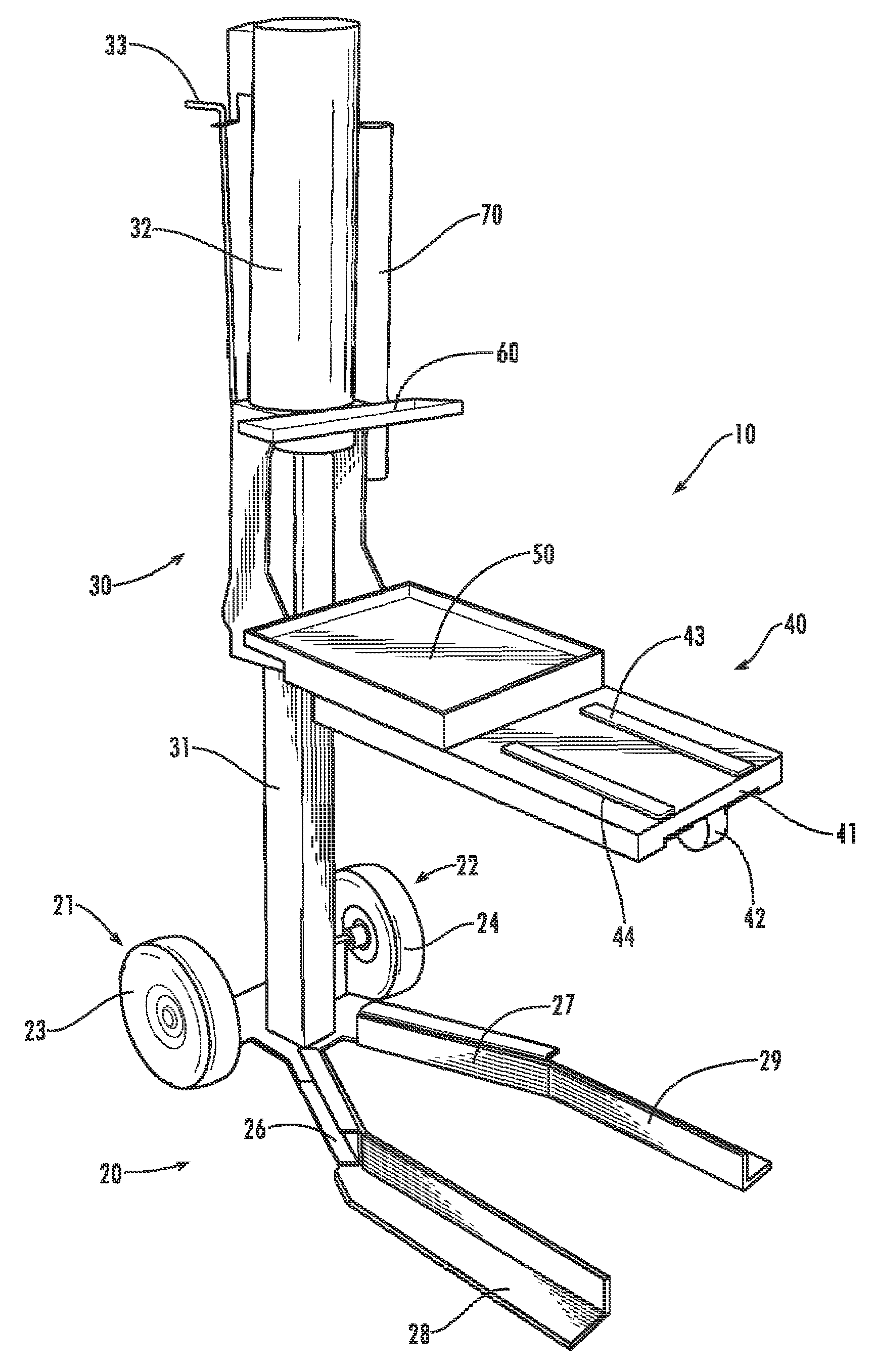
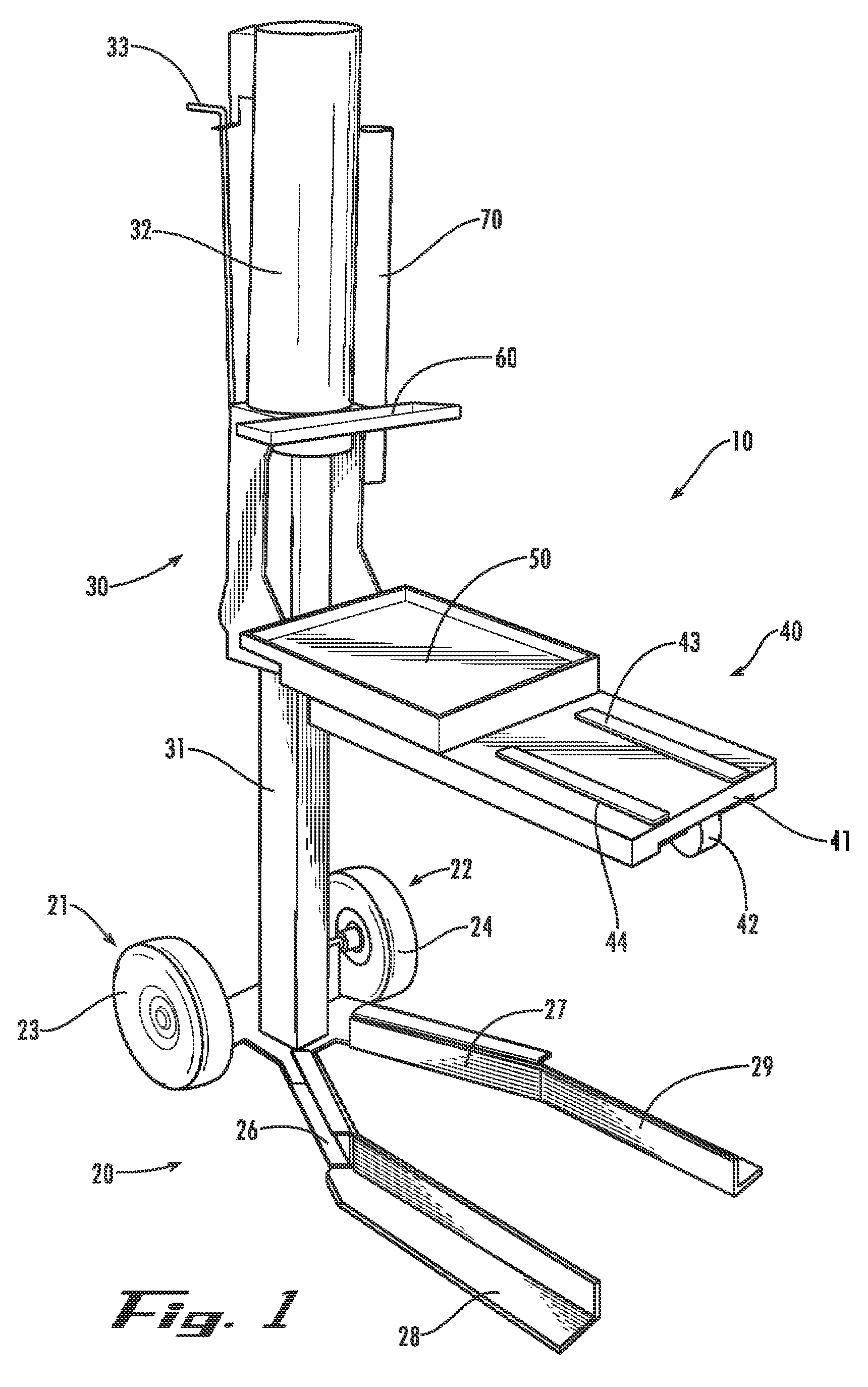
[0016]Referring now in detail to the drawing figures, wherein like reference numerals represent like parts throughout the several views, FIG. 1 shows an engine lift 10 according to a preferred form of the invention. It will be understood by those skilled in the art that the engine lift 10 can be used to lift engine blocks or entire engines. The engine lift 10 includes a base frame 20 having a pair of wheels indicated at 21 and 22. The wheels have rubber tires 23, 24. The base 20 also includes a laterally extending base, here shown in the form of legs comprising first and second extensions or proximal leg portions 26 and 27, which together form a sort of yoke in that the proximal leg portions 26 and 27 are splayed apart. The legs also include end portions or extensions 28 and 29 which extend parallel to one another and at an angle relative to the first (proximal) portions 26 and 27. In a commercial embodiment, these end portions comprise sections of angle iron, preferably having a wi...


PUM


Abstract

An engine lift for raising, lowering and supporting an engine block or engine includes a movable frame that has ground-engaging wheels and an elongate base that extends laterally. A support shelf is provided for supporting an engine block or engine and includes a non-marring surface upon which the engine or engine block can rest. A tool tray is positioned near the support shelf and an air cylinder is coupled to the movable frame for raising and lowering the support shelf. A second tool tray is provided, as is a tool holster for supporting and storing a bar-like tool. The elongate base comprises a pair of low-profile elongate base legs for slipping beneath the frame of a mobile engine stand (when used in conjunction with a mobile engine stand).

Description

CROSS REFERENCE TO RELATED APPLICATION[0001]The benefit of the filing date of U.S. provisional patent application Ser. No. 60 / 759,867, filed Jan. 18, 2006, entitled ENGINE LIFT, is hereby claimed, and the specification thereof is incorporated herein by this reference.FIELD OF THE INVENTION[0002]The present invention relates generally to tools and in particular relates to a tool used in the servicing and / or rebuilding of automotive engines.BACKGROUND OF THE INVENTION[0003]In servicing automotive engines, such as when rebuilding the engine, it is often necessary to raise or lower the entire engine or a major portion of the engine. Also, it often occurs that the engine needs to be moved about as well. This raising and lowering of the engine or moving the engine about occurs in automotive machine shops, automotive garages, and in home garages.[0004]Unfortunately, the engine in most automobiles is quite heavy. Indeed, even the engine “block” can weigh more than 200 pounds. The engine blo...

Claims


Application Information

Patent Timeline
IPC IPC(8): B66F3/24
CPCB25H1/0007B66F7/16B66F5/04
Inventor GOZA, TOMMY J.
Owner GOZA TOMMY J
Why Eureka
Try Eureka