Quick coupler lock system

a coupler lock and quick technology, applied in the field of mechanical systems, can solve problems such as prior safety lock activation

Inactive Publication Date: 2007-07-19
PSM
View PDF15 Cites 61 Cited by
  • Summary
  • Abstract
  • Description
  • Claims
  • Application Information

AI Technical Summary

Problems solved by technology

However, it is observed that this prior safety lock is activated only upon a loss of hydraulic pressure.

Method used


Image

  • Quick coupler lock system
  • Quick coupler lock system
  • Quick coupler lock system

Examples


Embodiment Construction

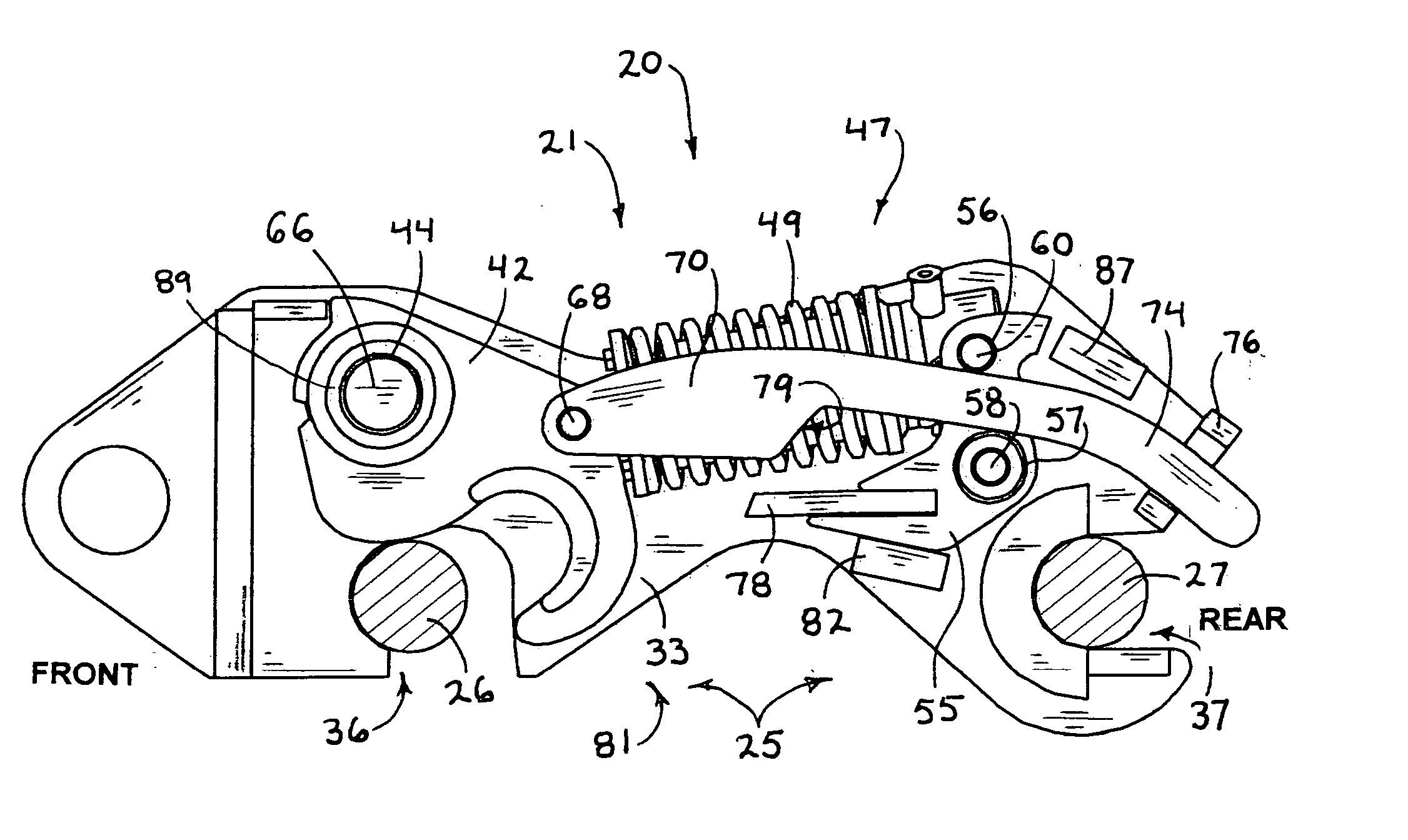
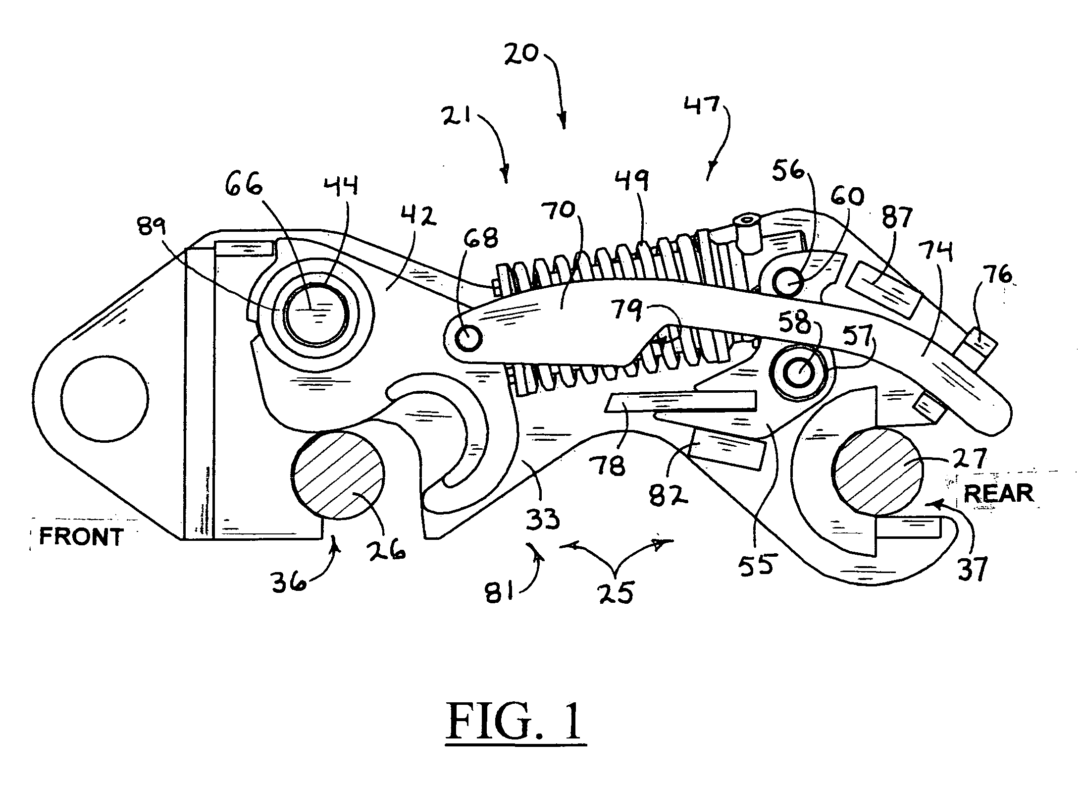
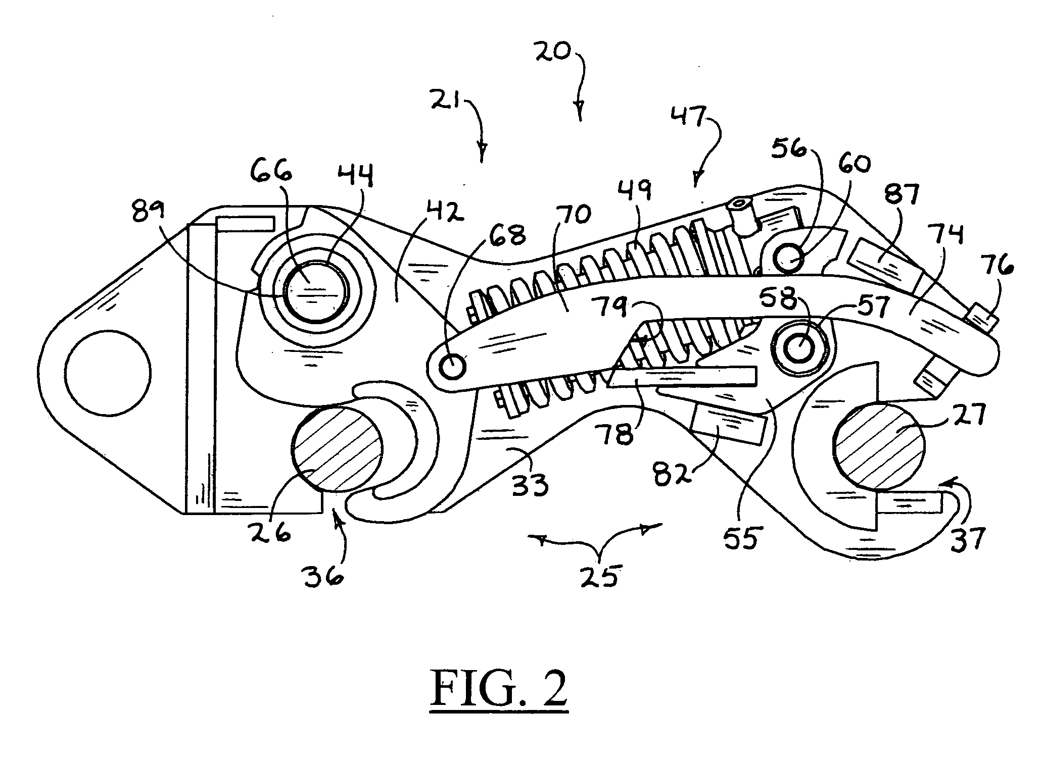
[0019] The present invention relates to a coupler lock system, useful as a safety for preventing the unwanted release of an auxiliary attachment from a “quick coupler,” also referred to herein as a coupler assembly. As discussed above, quick couplers are widely utilized in the easy connection and release of auxiliary attachments, to and from heavy equipment booms, typically while at a work site, or in the field. These heavy equipment booms are typically actuated by hydraulic mechanisms, and controlled by an operator. With a quick coupler, a heavy equipment boom may switch easily from one attachment to another, as the job requires. For example, a bucket may need to be switched out with a grapple, or a broken bucket may need to be changed-out for repair.

The Quick Coupler Lock System

[0020]FIGS. 1 through 13 show features of a preferred embodiment of a coupler assembly 21, which includes the coupler lock system 20 of the present invention. The coupler assembly is mountable to a boom ...


PUM


Abstract

A quick coupler lock, for use as a safety to engage an attachment, such as a bucket or scoop, to a heavy equipment armature, as found in backhoes and excavators. The coupler lock prevents the unwanted release of auxiliary attachments. The coupler lock includes a coupler frame with a pin grabber, and a coupler hook rotated to engage a pin. The rotation of the coupler hook is accomplished by the extension or retraction of a coupler actuator, preferably a hydraulic cylinder held within a spring. The coupler actuator hingably connects to a pivoting lock lever. The action of the coupler actuator rotates the lock lever about the lever pin. A lock bar hingably attaches to the coupler hook and rotates with the coupler hook. The lock lever includes an arm that contacts the lock bar, to prevent movement of the coupler hook and prevent the unwanted release of the pin.

Description

TECHNICAL FIELD [0001] The invention relates to a mechanical system for safely engaging an attachment such as a bucket or scoop, to a hydraulic armature, as employed with conventional heavy equipment, such as backhoes and excavators. BACKGROUND OF THE INVENTION [0002] Heavy equipment manufacturers typically employ hydraulic actuators to move and articulate arms, booms, buckets and auxiliary tools. These auxiliary tools can include hydraulically actuated attachments, such as scoops, fingers and grapples. A savings in the cost of purchasing and operating heavy equipment, such as backhoes and excavators, can be realized if attachments are removable and interchangeable. This enables a particular piece of heavy equipment to perform more than one function, increasing the usefulness of the equipment and possibly eliminating the need to purchase additional equipment. However, the ability to quickly switch from one attachment to another, creates the need for a quick coupling system that mini...

Claims


Application Information

Patent Timeline
Patent Type & Authority Applications(United States)
IPC IPC(8): B66C23/00
CPCE02F3/3618E02F3/3663E02F3/365E02F3/3622
Inventor HART, MICHAEL D.PISCO, WALTER J.
Owner PSM
Why Eureka
Try Eureka