Pseudo-isothermal catalytic reactor

Inactive Publication Date: 2007-07-19
CASALE SA
View PDF6 Cites 0 Cited by
  • Summary
  • Abstract
  • Description
  • Claims
  • Application Information

AI Technical Summary

Benefits of technology

[0013] Surprisingly, it has been found that, by arranging heat exchangers inside a reactor in the aforementioned way, it is possible to use exchangers all generally of the same size, thus solving the technical problem and overcoming the drawbacks of the prior art as described above.

Problems solved by technology

Although advantageous from various points of view, such heat exchange units have a serious and recognized drawback.
Indeed, when one wishes to use the entire mass of catalyst as uniformly as possible in the heat exchange, as is generally required, such heat exchange units necessarily comprise different sized plated heat exchangers; for this reason, the production, the storage and the transportation of such exchangers is very laborious and not cost-effective, just as the assembly and operation of the heat exchange units of which they consist is also laborious and not cost-effective.

Method used


Image

  • Pseudo-isothermal catalytic reactor
  • Pseudo-isothermal catalytic reactor
  • Pseudo-isothermal catalytic reactor

Examples


Embodiment Construction

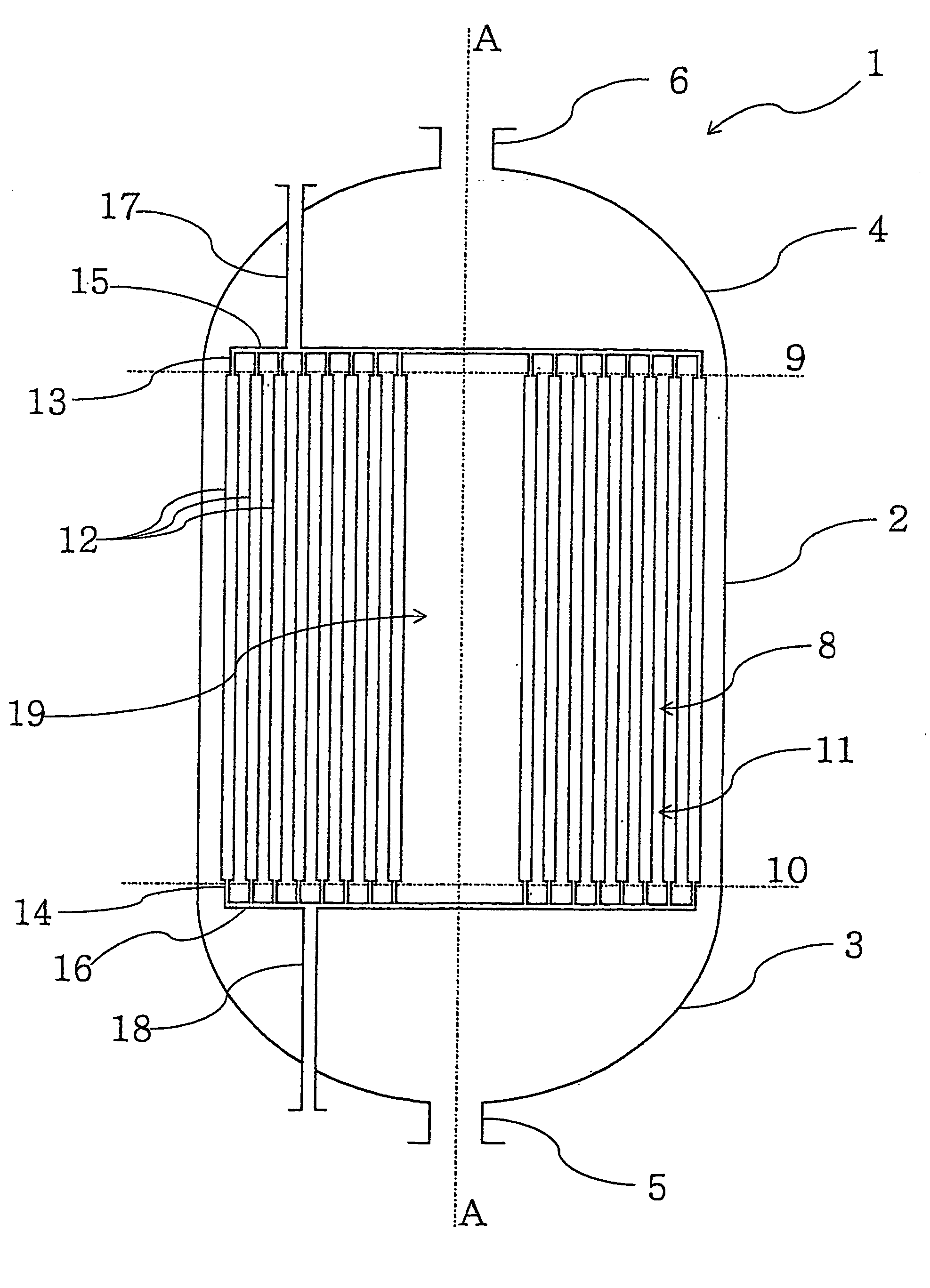
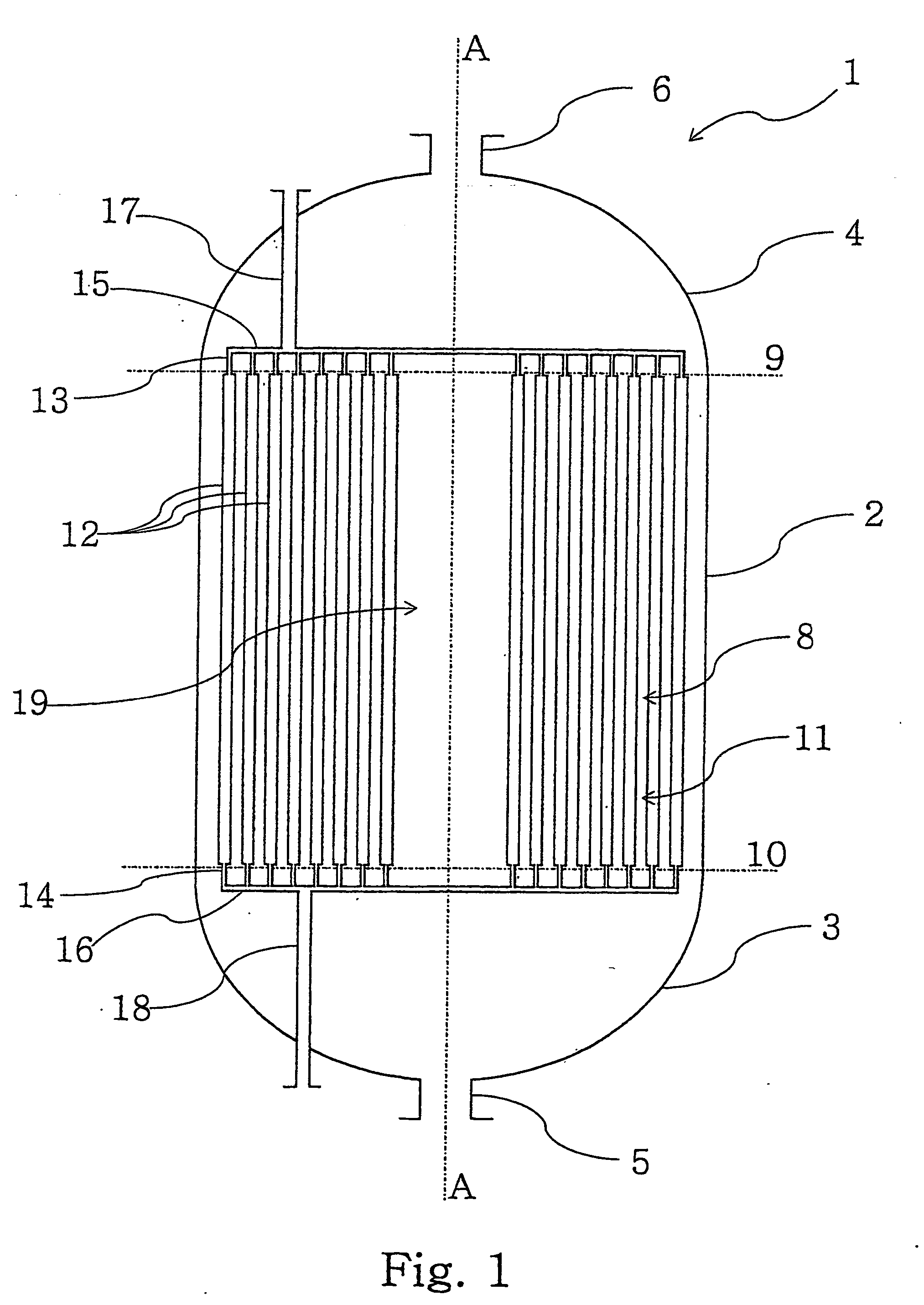
[0019] With reference to FIGS. 1-4, an axial pseudo-isothermal chemical reactor, with a vertical axis A-A, comprising a substantially cylindrical shell 2, closed at the opposite ends by lower 3 and upper 4 bottoms respectively, is globally and schematically indicated with 1.

[0020] The lower bottom 3 is equipped with a mouth 5 for the discharge of the reaction products, whereas the upper bottom 4 is equipped with an opening 6 for the input of the reactants.

[0021] Inside said shell 2 a reaction zone 8 is defined, representatively situated between an upper line 9 and a lower line 10, to hold a predetermined catalytic bed 11 (supported in a per se known way and therefore not represented).

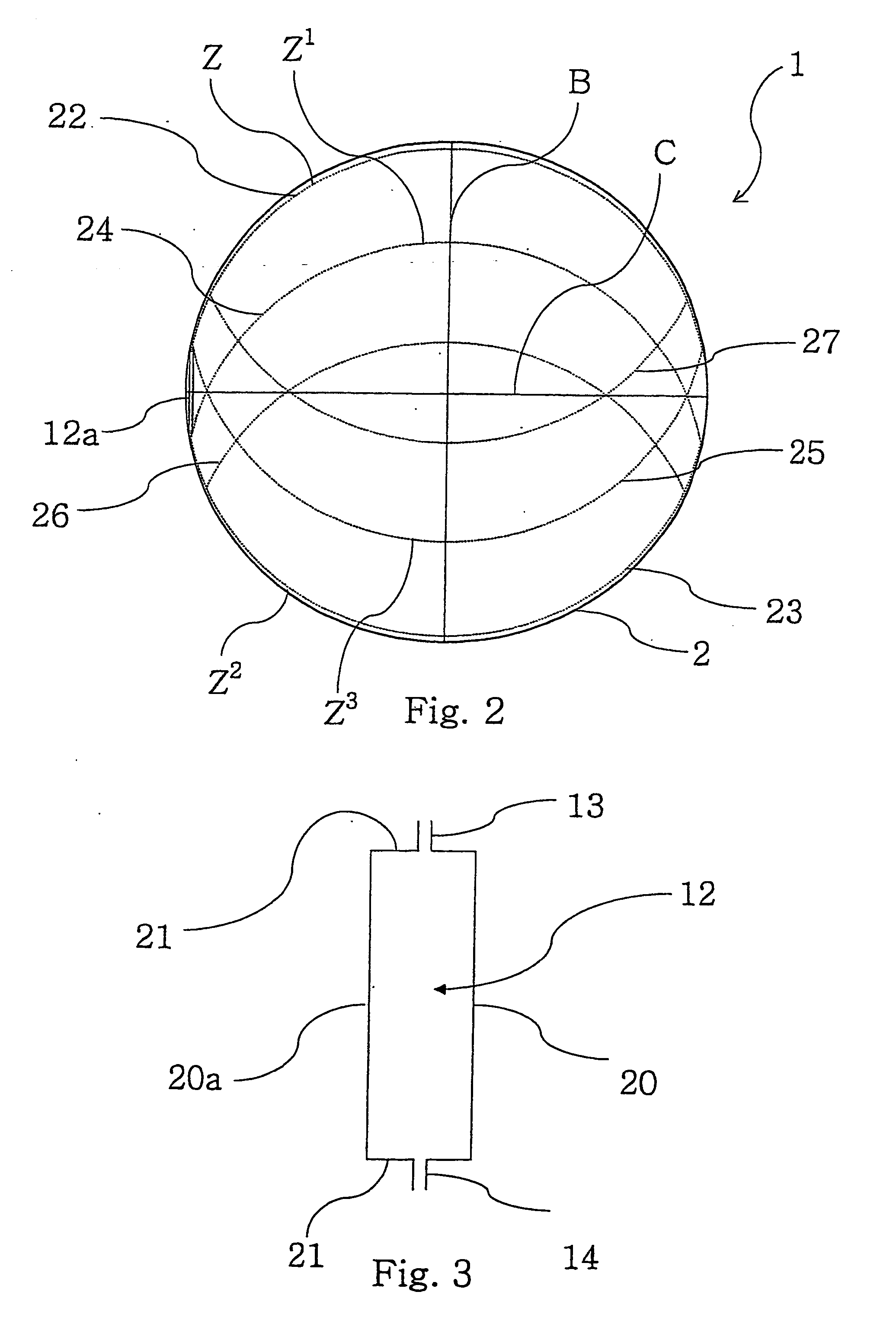
[0022] Inside said reaction zone 8, and in particular in said catalytic bed 11, a plurality of flat, boxed, plate-shaped heat exchangers 12 having the shape of a parallelepiped is positioned.

[0023] Such exchangers 12 have long sides 20, 20a (FIG. 3) parallel to the axis A-A and short sides 21 parall...


PUM


Abstract

Pseudo-isothermal chemical reactor (1) for catalytic reactions with a vertical axis, comprising a substantially cylindrical shell (2), Closed at the opposite ends by upper (4) and lower (3) bottoms respectively, a reaction zone (8) in which a catalytic bed (11) and a plurality of flat, boxed, plate-shaped heat exchangers (12), having the shape of a parallelepiped and having long sides parallel to said vertical axis and short sides perpendicular to it, situated in said reaction zone and supported in an arrangement on parallel cords at a predetermined distance.

Description

FIELD OF APPLICATION [0001] The present invention, in its most general aspect, refers to a pseudo-isothermal chemical reactor for catalytic reactions, comprising a substantially cylindrical shell closed at the opposite ends by respective bottoms, a reaction zone defined in said shell and in which at least one catalytic bed and a plurality of plate heat exchangers situated in said reaction zone are supported. [0002] In the rest of the description and in the subsequent claims, with the term “pseudo-isothermal reactor” we mean to identify a reactor for chemical reactions in which the reaction temperature is controlled within a limited range of values around a predetermined optimal value. [0003] In particular, the present invention concerns a reactor of the aforementioned type structured so that, with reference to the main axis of the reactor, the crossing of the reaction zone by the reactants and the reaction products takes place in the axial direction. PRIOR ART [0004] As is known, th...

Claims


Application Information

Patent Timeline
IPC IPC(8): B01J8/02F28D9/00
CPCB01J8/025F28D9/0006B01J2208/0015B01J8/0285
Inventor FILIPPI, ERMANNORIZZI, ENRICOTAROZZO, MIRCO
Owner CASALE SA
Why Eureka
Try Eureka