Wire guide having distal coupling tip

a wire guide and distal coupling technology, applied in the field of wire guides, can solve the problems of proximal tortuosity of the vasculature wire guide tip may prolapse away from the site, etc., to achieve the effect of easily and reliably traversing through the body lumen

Active Publication Date: 2007-07-19
COOK MEDICAL TECH LLC
View PDF63 Cites 25 Cited by
  • Summary
  • Abstract
  • Description
  • Claims
  • Application Information

AI Technical Summary

Benefits of technology

[0008] The present invention provides a supporting wire guide for intracorporeal procedures that may be easily and reliably traversed through a body lumen to a position proximate a previously introduced wire guide. The supporting wire guide is a coupling wire guide that is structured to be slidably coupled to the previously introduced wire guide. In one embodiment constructed in accordance with the teachings of the present invention, the coupling wire guide generally includes a main body and a tip portion connected to the distal end of the main body. The tip portion includes a coupling head defining a coupling passageway. The coupling head is operable between at least two positions including a first position generally aligned with the main body and a second position non-aligned with the main body.
[0009] According to more detailed aspects of the invention, the tip portion is preferably constructed of a resilient material, and most preferably a plastic overmolded onto the distal end of the main body. The tip portion includes a neck connected to the coupling head which flexes to permit the coupling head to transition between the first and second positions. The neck has an outer diameter that is less than the outer diameter of the coupling head, and preferably includes one or more radially facing depressions to create a predetermined path along which the coupling head flexes between the first and second positions. An outer diameter of the coupling head is about equal to or less than the largest diameter of the remainder of the tip portion, thereby improving placement and translation of the coupling wire guide when not coupled to a previously introduced wire guide.

Problems solved by technology

Proximal tortuosity of the vasculature is problematic for all medical catheter devices such as atherectomy devices, angioplasty devices, stent delivery devices, and filter delivery devices.
Accordingly, wire guides are subjected to potentially conflicting requirements.
However, in some situations the wire guide tip may prolapse away from the site to which it is guiding the device.
For example, balloon angioplasty in vessels with proximal tortuosity has been associated with a higher incidence of acute complications and procedural failure due to the inability to cross lesions with a conventional floppy wire guide, and due to the inability of the wire guide to provide adequate support to the balloon catheter.
Heavy-duty wire guides, on the other hand, are generally not well suited as primary wire guides because of their stiffness and potential for causing injury to the vessel during introduction.
However, the navigation of the supplemental wire guide parallel to the first wire guide is an exacting and time consuming process in which additional difficulties are encountered.
For example, the second wire guide can cork screw or coil around the first wire guide, which may result in immobilization or unintended movement of the first wire guide, which in turn may require the retraction and re-feeding of the supplemental wire guide and / or the primary wire guide.
Moreover, if retraction of the supplemental wire guide is necessary, either of the wire guides may become contaminated and the entire process may need to be restarted with sterile components.
Additionally, when traversing through the heart of a patient, and particularly the ostium, the larger open space of the heart makes identical placement of the supplemental wire guide somewhat difficult.

Method used


Image

  • Wire guide having distal coupling tip
  • Wire guide having distal coupling tip
  • Wire guide having distal coupling tip

Examples


Embodiment Construction

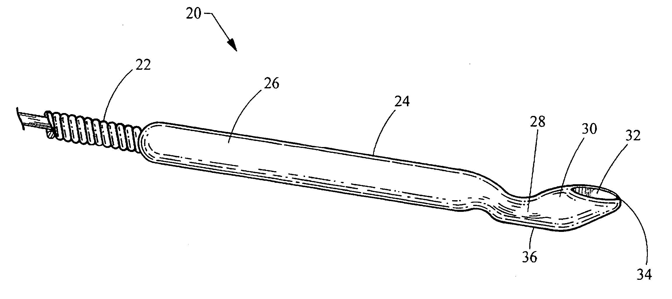
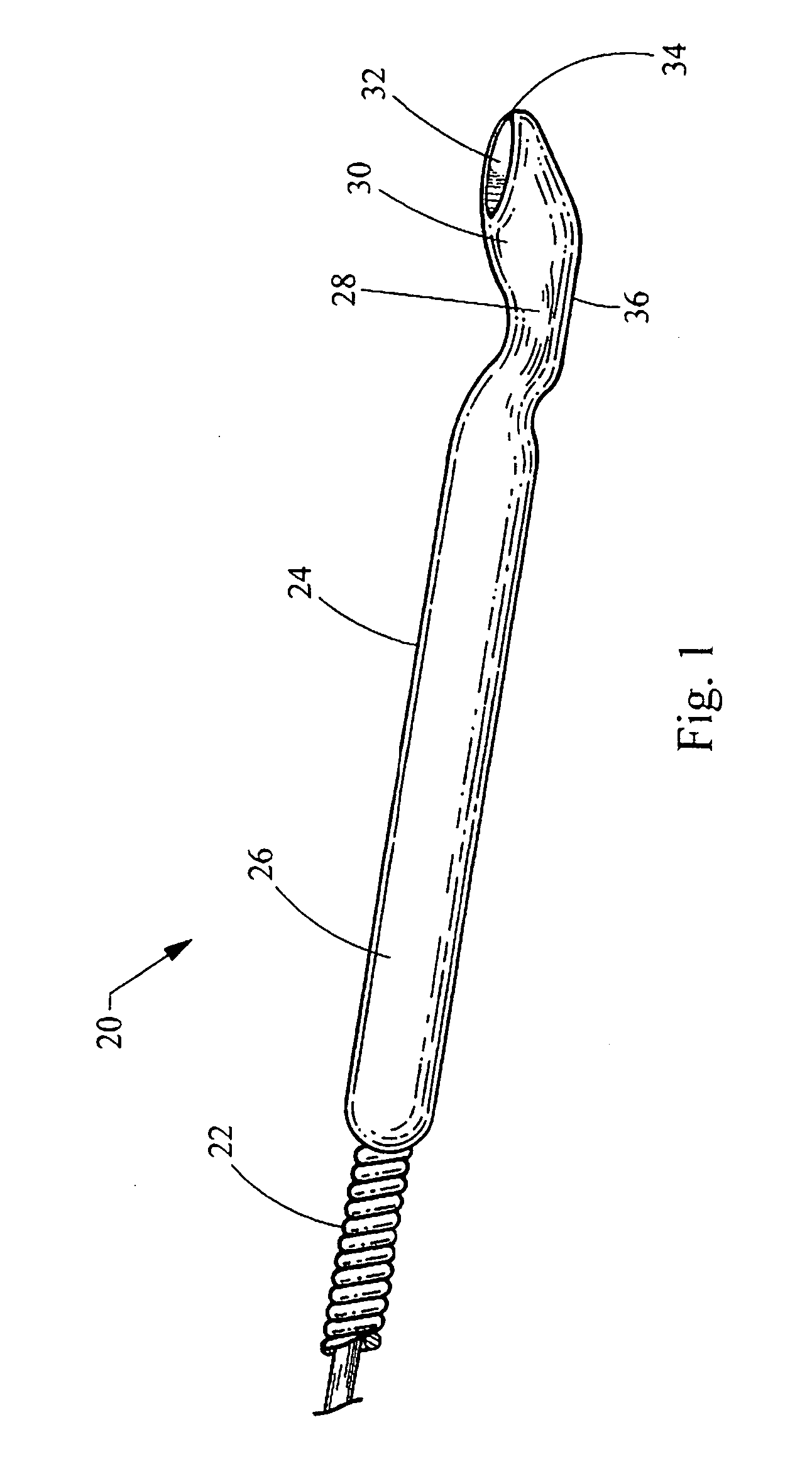
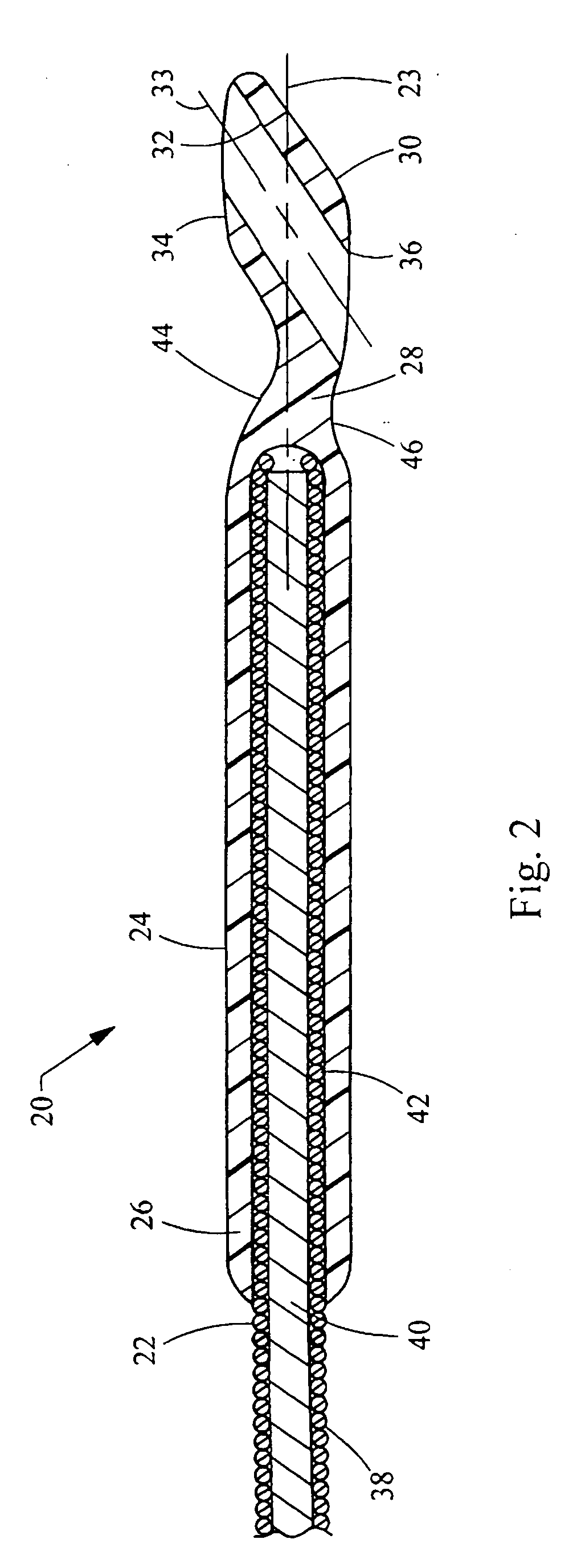
[0019] Turning now to the figures, FIGS. 1 to 3 depict a coupling wire guide 20 constructed in accordance with the teachings of the present invention. The coupling wire guide 20 is easily and reliably coupled to and traversed along a previously introduced wire guide 10, and also is easily used alone by maintaining a relatively low profile when decoupled. While wire guides are generally used in percutaneous interventional procedures, it will be recognized by those skilled in the art that the wire guide of the present invention may also be employed non-percutaneously, such as in endoscopic or other intracorporeal procedures. As best seen in FIG. 1, the coupling wire guide 20 generally includes a main body 22 and a tip portion 24. The tip portion includes an attachment section 26, a neck 28 and a coupling head 30. The coupling head 30 defines a coupling passageway 32 having a distal port 34 and a proximal port 36 through which the previously introduced wire guide 10 passes, as shown in...


PUM


Abstract

A coupling wire guide structured to be slidably coupled to a previously introduced wire guide. The coupling wire guide includes a main body having a distal section. The distal section includes an outer wire disposed over a safety wire. A loop wire is connected to the safety wire at two axially spaced points. At least a portion of the loop wire is positioned outside of the outer wire to define a loop area sized to receive the previously introduced wire guide.

Description

CROSS-REFERENCE TO RELATED APPLICATIONS [0001] This application claims the benefit of U.S. Provisional Application Ser. No. 60 / 758,880 filed on Jan. 13, 2006, entitled “WIRE GUIDE HAVING DISTAL COUPLING TIP”, the entire contents of which are incorporated herein by reference.FIELD OF THE INVENTION [0002] This invention relates generally to a wire guide for use in intracorporeal procedures, and more particularly relates to the construction of a wire guide to be coupled to a previously introduced wire guide for assistance during interventional procedures in vessels with proximal tortuosity, or as a more substantial wire guide for angioplasty procedures, stenting procedures, and other device placement procedures and their related devices. BACKGROUND OF THE INVENTION [0003] Proximal tortuosity of the vasculature is problematic for all medical catheter devices such as atherectomy devices, angioplasty devices, stent delivery devices, and filter delivery devices. Wire guides are therefore t...

Claims


Application Information

Patent Timeline
Patent Type & Authority Applications(United States)
IPC IPC(8): H01R4/24
CPCA61M25/09A61M2025/09175A61M25/0905
Inventor MELSHEIMER, JEFFRY S.HRUSKA, CHRISTOPHER L.
Owner COOK MEDICAL TECH LLC
Why Eureka
Try Eureka