Intra-subject position detection system

a position detection system and intra-subject technology, applied in the field of intra-subject position detection system, can solve the problem that the position of the capsule endoscope in the subject cannot be detected with high accuracy

Inactive Publication Date: 2007-07-19
OLYMPUS CORP
View PDF20 Cites 149 Cited by
  • Summary
  • Abstract
  • Description
  • Claims
  • Application Information

AI Technical Summary

Benefits of technology

[0011] An intra-subject position detection system according to one aspect of the present invention includes a subject insertable device that is introduced into a subject and moves through the subject; and a position detecting device that is arranged outside the subject and obtains position information of the subject insertable device inside the subject. The subject insertable device includes a magnetic field generator that generates a magnetostatic field. The position detecting device includes a magnetic field detector t

Problems solved by technology

The conventional capsule endoscope system, however, is disadvantageous in that the po

Method used


Image

  • Intra-subject position detection system
  • Intra-subject position detection system
  • Intra-subject position detection system

Examples


first embodiment

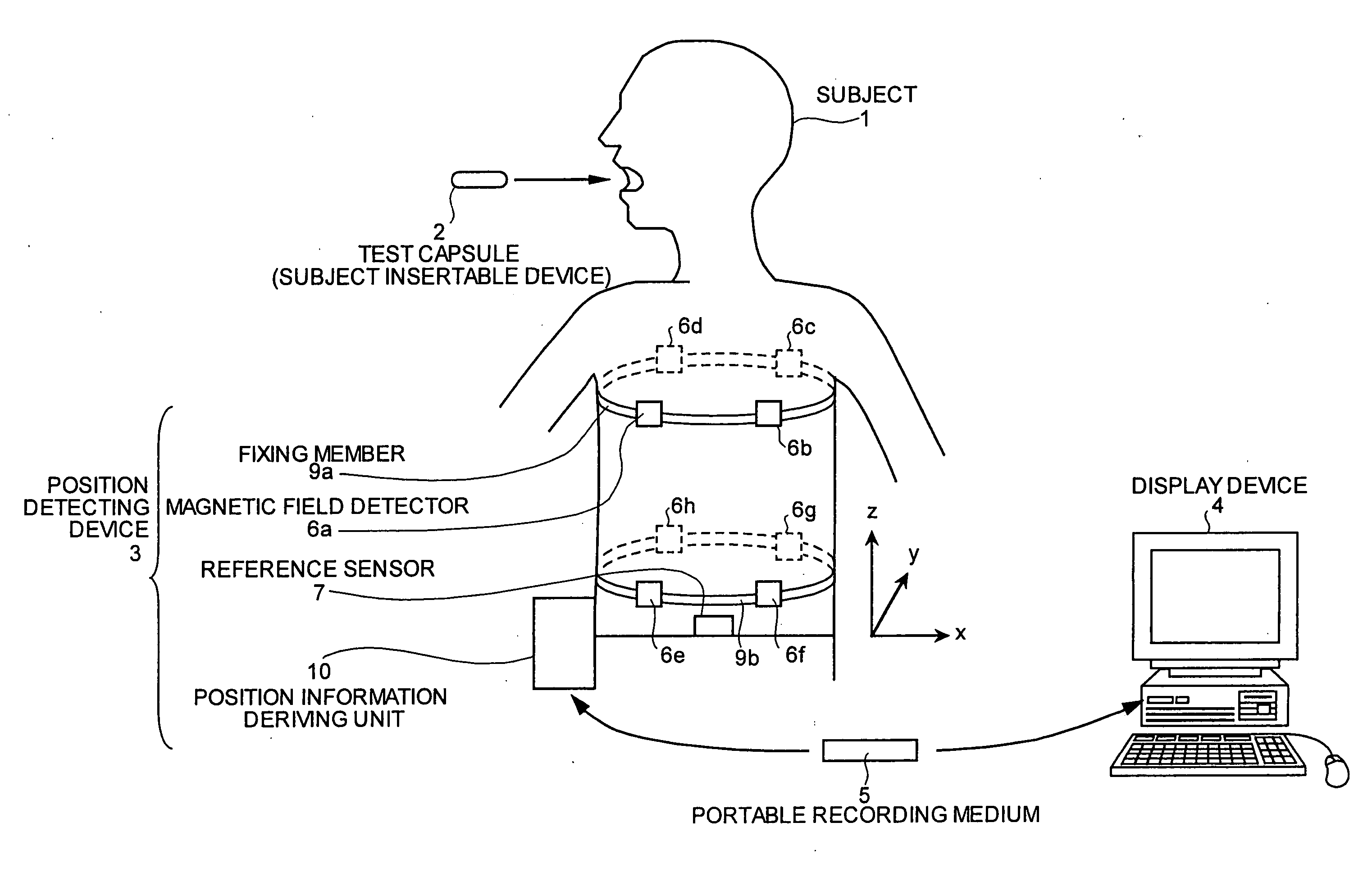
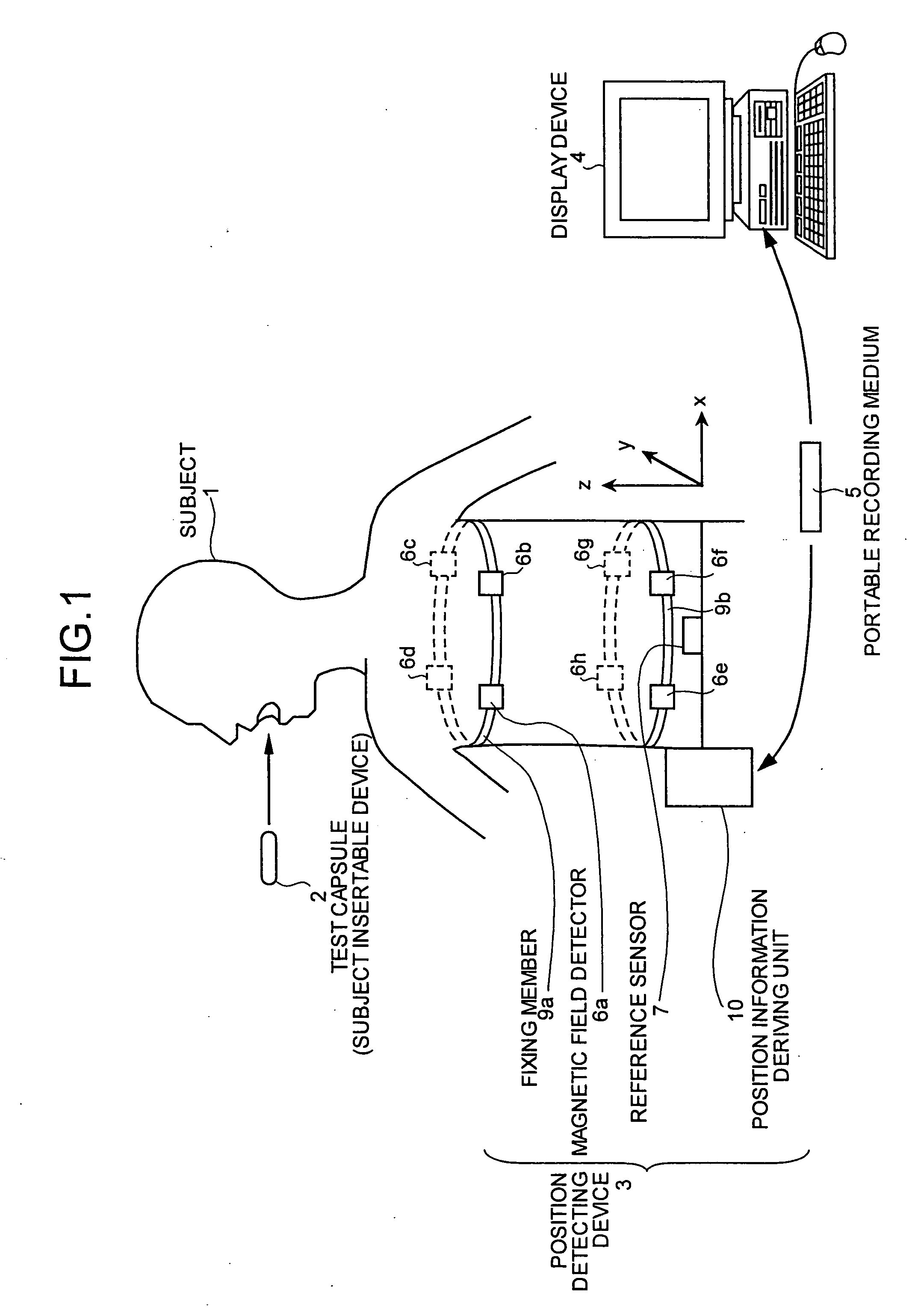
[0039] Before a capsule endoscope or the like is introduced into the subject 1, a preliminary examination is carried out with the test capsule 2. The test capsule 2 checks whether there is a portion with stenosis, where passage of the capsule endoscope is difficult, in the subject or not. The intra-subject position detection system examines how the test capsule 2 moves through inside the subject 1, and has a highly accurate position detection mechanism to realize such examination.

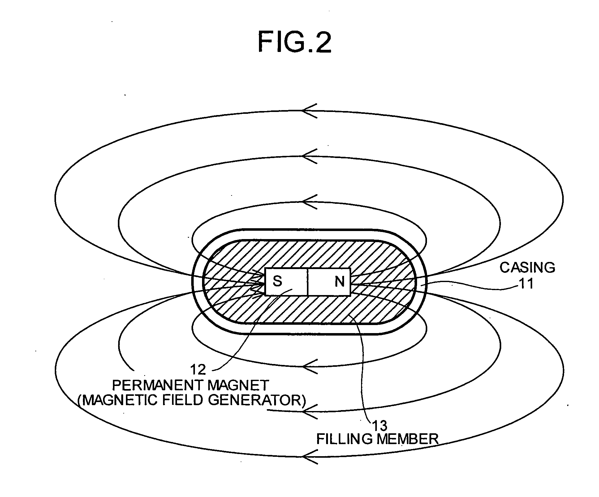
[0040]FIG. 2 is a schematic diagram of a structure of the test capsule 2. As shown in FIG. 2, the test capsule 2 includes a casing 11, a permanent magnet 12, and a filling member 13. The casing 11 is formed in a capsule shape similar to a shape of a casing of the capsule endoscope. The permanent magnet is arranged inside the casing 11. The filling member 13 serves to fill up a gap between an inner surface of the casing 11 and the permanent magnet 12.

[0041] The casing 11 is formed, for example, of a biocom...

fourth embodiment

[0085] The position derivation by the magnetic field detector 6 in the intra-subject position detection system of the fourth embodiment will be described. First, the reference sensor 50 adjusts the orientation of the array antenna 51 by the orientation adjuster 53 while searching for a direction where the reference sensor 50 can receive the radio signal sent from the magnetic field detector 6. When the orientation set by the orientation adjuster 53 matches with the direction of the magnetic field detector 6, the reference sensor 50 receives the radio signal through the array antenna 51. Then, the received signal strength detecting unit 26 detects the strength of the received radio signal. At the same time, the distance deriving unit 27 derives the distance between the reference position at which the array antenna 51 is positioned and the magnetic field detector 6. Then, information concerning the distance is transmitted to the position deriving unit 28.

[0086] On the other hand, the ...

fifth embodiment

[0098] The storage unit 74 has a function of storing the image data as well as the position information of the capsule endoscope 55 derived by the capsule position calculator 34. Since the intra-subject position detection system of the fifth embodiment has such a structure, the display device 4 can present an image of inside the subject 1 together with an indication of a position of the image pick-up inside the subject 1.

[0099] The position information deriving unit 70 has a structure as a transmission unit that generates the power supply signal and the travel state information signal both to be transmitted to the capsule endoscope 55, and transmits the generated signals to the power supply antennae B1 to Bm. Specifically, as shown in FIG. 3, the position information deriving unit 70 includes an oscillator 75, a control information input unit 76, a superposing circuit 77, and an amplifier circuit 78. The oscillator 75 has a function of generating the power supply signal and a functi...


PUM


Abstract

An intra-subject position detection system includes a subject insertable device introduced into a subject, moving through the subject; and including a magnetic field generator that generates a magnetostatic field. The system also includes a position detecting device arranged outside the subject and obtaining position information of the subject insertable device inside the subject. The position detecting device also includes a magnetic field detector that is arranged on the subject at a time of use and detects a strength of the magnetostatic field output from the magnetic field generator; a reference sensor that derives a position of the magnetic field detector relative to a reference position on the subject; and a position deriving unit that derives a position of the subject insertable device inside the subject based on the magnetic field strength and the position of the magnetic field detector.

Description

CROSS-REFERENCE TO RELATED APPLICATIONS [0001] This application is a continuation of PCT international application Ser. No. PCT / JP2005 / 001964 filed Feb. 9, 2005 which designates the United States, incorporated herein by reference, and which claims the benefit of priority from Japanese Patent Applications No. 2004-095882, filed Mar. 29, 2004; and No. 2004-109049, filed Apr. 1, 2004, incorporated herein by reference. BACKGROUND OF THE INVENTION [0002] 1. Field of the Invention [0003] The present invention relates to an intra-subject position detection system which includes a subject insertable device which is introduced into a subject and moves through the subject, and a position detecting device which is arranged outside the subject and obtains position information of the subject insertable device in the subject. [0004] 2. Description of the Related Art [0005] In recent years, a swallowable-type capsule endoscope is proposed in the field of endoscope. The capsule endoscope is equippe...

Claims


Application Information

Patent Timeline
IPC IPC(8): A61B5/05A61B5/06A61B5/07
CPCA61B1/00016A61B1/041A61B5/062A61B1/0684A61B5/073A61B5/6831A61B5/065
Inventor HONDA, TAKEMITSUHIRAKAWA, KATSUMIKIMOTO, SEIICHIRONAGASE, AYAKOSASAGAWA, KATSUYOSHISUZUKI, KATSUYANAKATSUCHI, KAZUTAKA
Owner OLYMPUS CORP
Why Eureka
Try Eureka