Method, system and program product for facilitating debugging of simulation results obtained for an optimized simulation model of a device design having hierarchically-connected components

a simulation model and hierarchical connection technology, applied in the field of simulation results debugging and tracing, can solve the problems of tedious and time-consuming solution and optimization of simulation model

Inactive Publication Date: 2007-07-19
IBM CORP
View PDF17 Cites 20 Cited by
  • Summary
  • Abstract
  • Description
  • Claims
  • Application Information

AI Technical Summary

Benefits of technology

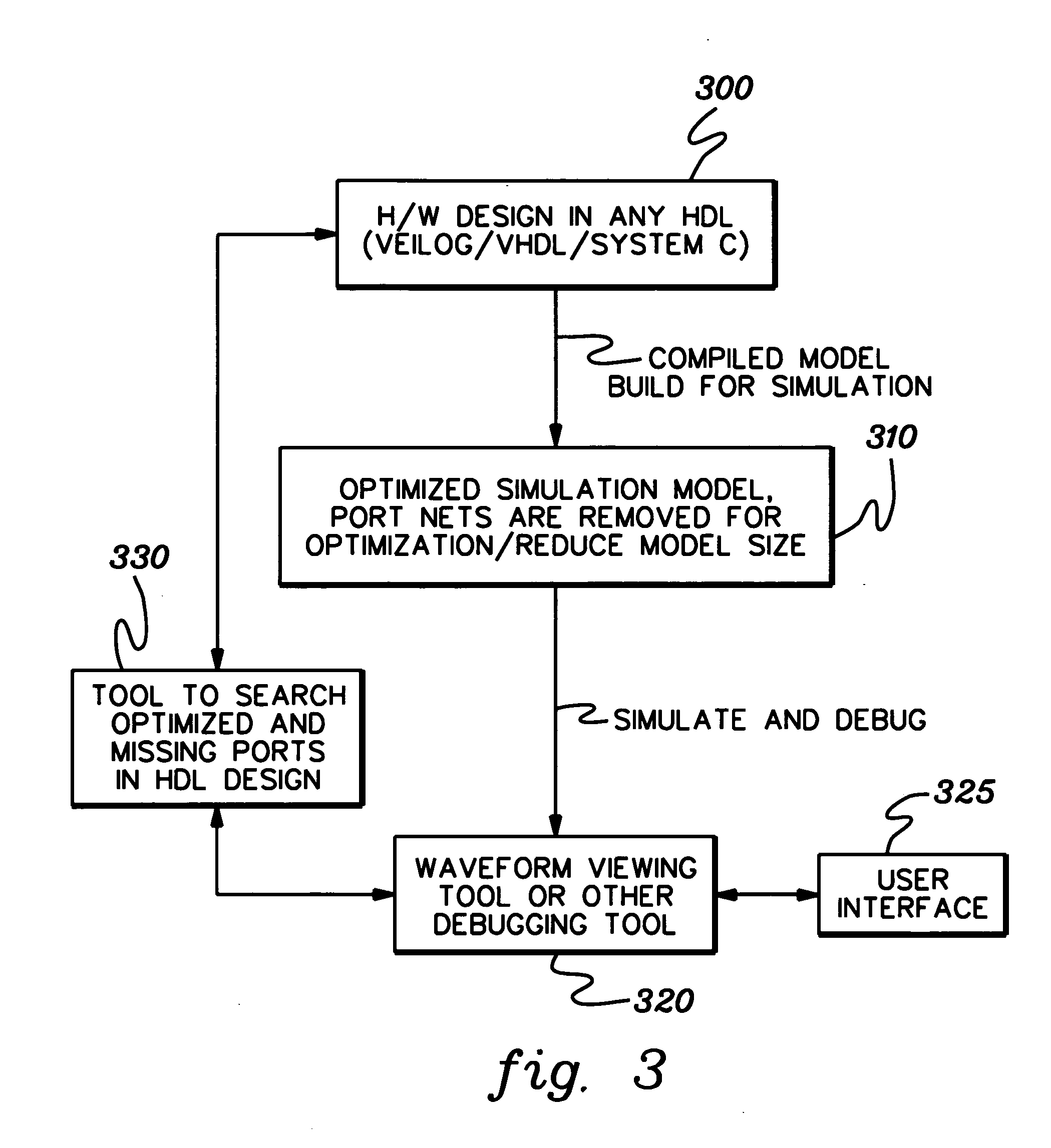
[0006] In accordance with an aspect of the present invention, a computer-implemented method is provided for facilitating debugging of simulation results obtained for an optimized simulation model of a device design having hierarchically-connected components. The method includes: receiving a component port name of the device design to be searched; automatically checking a hardware descriptive language description of the device design for a next higher level component of the device that instantiates the component having the component port name to be searched; locating a signal name in the next higher level component that is connected to the port identified by the component port name; and outputting the signal name as a signal that drives the named component port when the signal is other than a port signal of the next higher level component.

Problems solved by technology

However, such an optimized simulation model may be a problem when a failure is to be debugged that requires the component ports to be examined.
The problem is encountered with component input ports, but in certain cases may also arise with output ports.
This is not always the best choice because of time, space and simulation speed considerations.
This solution can be very tedious and time consuming, and is therefore generally undesirable.

Method used


Image

  • Method, system and program product for facilitating debugging of simulation results obtained for an optimized simulation model of a device design having hierarchically-connected components
  • Method, system and program product for facilitating debugging of simulation results obtained for an optimized simulation model of a device design having hierarchically-connected components
  • Method, system and program product for facilitating debugging of simulation results obtained for an optimized simulation model of a device design having hierarchically-connected components

Examples


example 1

Assume that the user wants to know the state of port I0 of component C2. A full hierarchy component port name is provided as “device.C1.C2.I0”. Referencing the flowchart of FIG. 4, the following steps are involved:

[0037] Step 1: User inputs the port name and component name of interest, named “comp_test”=“device.C1.C2.I0”. [0038] Step 2: “comp_test” is not at top of design hierarchy. Go to Step 4. [0039] Step 4: Component that instantiated C2 is C1, “comp_top”32 C1. Go to Step 5. [0040] Step 5: Checking the HDL description of C1, shows that port I0 of C2 is directly connected to port I0 of C1. Go to Step 6. [0041] Step 6: Port I0 of C2 is connected to port name 10 of C1. Go to Step 8. [0042] Step 8: New “comp_test”32 C1. Go to Step 2. [0043] Step 2: This “comp_test” (C1) is also not at top of design hierarchy. Go to Step 4. [0044] Step 4: Component that instantiated C1 is the device, “comp_top”=device. Go to Step 5. [0045] Step 5: Checking the HDL description of the device, shows t...

example 2

Assume that the user wants to know the state of port I1 of component C2. A full hierarchy component port name is provided as “device.C1.C2.I1”. Again referencing the flowchart of FIG. 4, the following steps are involved:

[0050] Step 1: User inputs the port name and component name of interest, named “comp_test”32“device.C1.C2.I1”. [0051] Step 2: “comp_test” is not at top of design hierarchy. Go to step 4. [0052] Step 4: Component that instantiated C2 is C1, “comp_top”=C1. Go to step 5. [0053] Step 5: Checking the HDL description of C1, shows that port I1 of C2 is directly connected to port I0 of C3. Go to step 6. [0054] Step 6: Port I1 of C2 is connected to port named I0 of C3. This wire (which connects port I1 of C2 with port 10 of C3) is an internal signal of C1. Go to step 7. [0055] Step 7: Return signal in C1 that connects port I1 of C2 and port 10 of C3 as the driver of the user initiated port search. [0056] Stop.

[0057] The detailed description presented above is discussed in ...


PUM


Abstract

A computer-implemented processing tool is provided for facilitating debugging of simulation results obtained for an optimized simulation model of a device having hierarchically-connected components. The tool includes: receiving a component port name of the device to be searched; automatically checking a hardware descriptive language description of the device for a next higher level component of the device that instantiates the component having the component port name to be searched; locating a signal name in the next higher level component that is connected to the port identified by the component port name; and outputting the signal name as a signal that drives the named component port when the signal is other than a port signal of the next higher level component. Otherwise, repeating the automatically checking and the locating when the signal name in the next higher level component is a port signal of a further higher level component.

Description

TECHNICAL FIELD [0001] This invention relates generally to debugging of simulation results during device design verification, and more particularly, to a facility for debugging and tracing simulation results for an optimized simulation model of a device having hierarchically-connected components. BACKGROUND OF THE INVENTION [0002] When a simulation of a device design is run during verification testing, and one or more failures in the simulation results need to be debugged or traced, it is often convenient to look at the simulation results depicted in a graphical interface as waveforms to find values of a signal(s) of interest at various times. The signal(s) of interest will almost always include a port(s) of the particular entity or component that is being examined. The task of the design / verification engineer is facilitated if the engineer is able to examine the values of the ports to a particular component, to determine what is happening inside the logic of the component. With cur...

Claims


Application Information

Patent Timeline
Patent Type & Authority Applications(United States)
IPC IPC(8): G06F11/00
CPCG06F17/5022G06F30/33
Inventor CHADHA, SUNDEEPPROCH, SUDHI R.
Owner IBM CORP
Why Eureka
Try Eureka