Eureka AIR delivers breakthrough ideas for toughest innovation challenges, trusted by R&D personnel around the world.

Method for indicating completion status of user initiated and system created tasks

a technology of user initiated and system created tasks, applied in the field of display, can solve the problems of preventing continuous execution of tasks, affecting the progress of tasks, and not progressing in a regular manner

Inactive Publication Date: 2007-07-19
IBM CORP
View PDF12 Cites 108 Cited by
  • Summary
  • Abstract
  • Description
  • Claims
  • Application Information

AI Technical Summary

Benefits of technology

[0008] It is an objective of the present invention to provide a display method and system that can display completion results for multiple tasks executing in a computing environment.
[0010] It is a third objective of the present invention to provide a display method and system that can indicate the occurrence of an error during the execution of a task such that a user can specifically observe where the error occurred during the task execution.
[0012] It is a fifth objective of the present invention to provide the ability to predict impending problems and initiate automated or manual actions as appropriate.
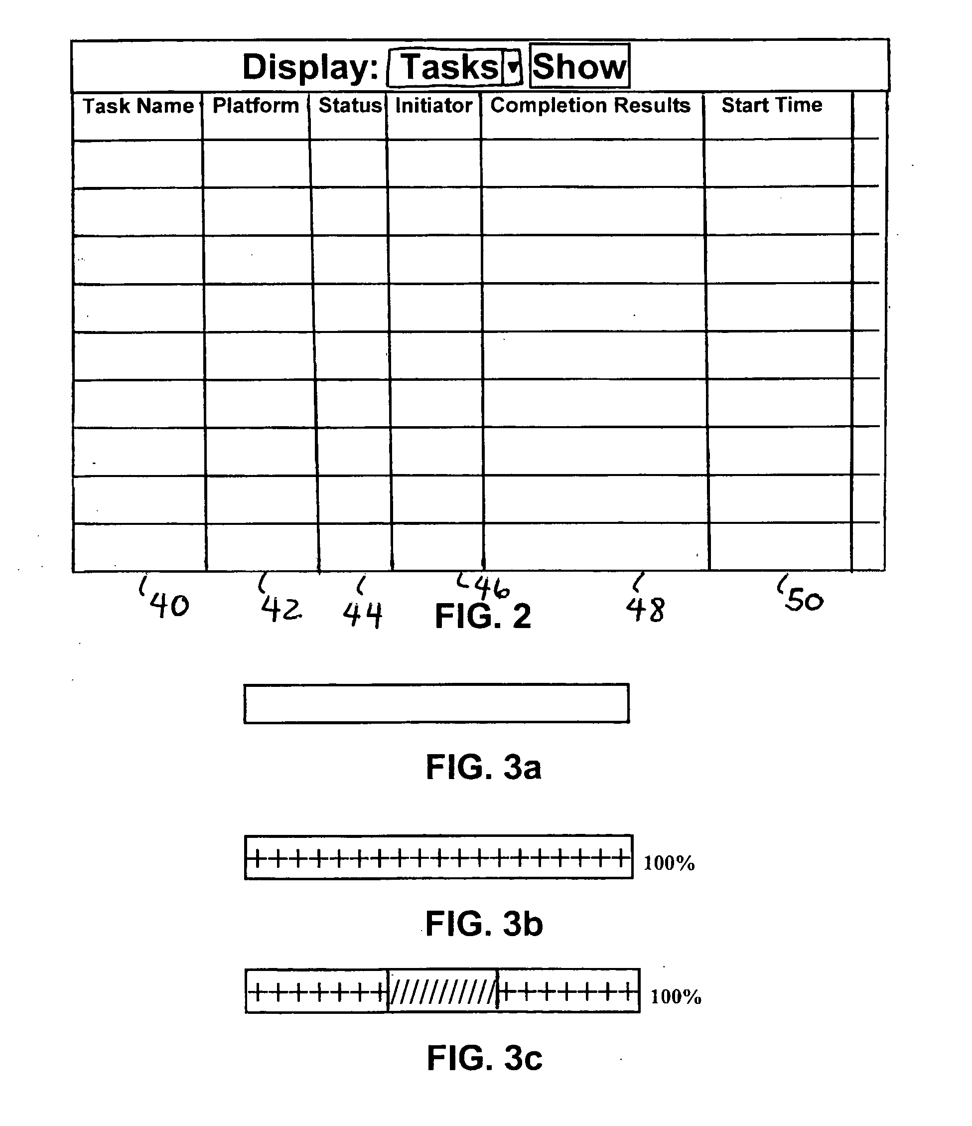
[0013] The present invention provides a display method and system that renders in a compact form, a comprehensive status of a functional task and its multiple operations' results during and after their execution of the task. This compact control allows the user to get a high level view of the overall completion status of the task.

Problems solved by technology

One problem with the status indication given to a user during a task is that often the percentage of the task already performed, or yet to be performed, does not progress in a regular manner.
For example, a file may take longer than expected to copy because of the time required to access the data on the device where it is stored.
It may also be possible that the computer has a large amount of high priority processor-intensive applications running concurrently with the task, thereby preventing continuous execution of the task.
Other delays may be caused by communication speed degradation or communication interruptions.
In some situations, an error message may indicate some problem with the execution of the task.
However, there is nothing in the display that points to a potential cause of the error.
However, the pie-shape charts are not compact enough and they require more UI estate to allocate.
A current problem is that the users may not be able to understand the impact of the overall tasks that have been initiated.

Method used


Image

  • Method for indicating completion status of user initiated and system created tasks
  • Method for indicating completion status of user initiated and system created tasks
  • Method for indicating completion status of user initiated and system created tasks

Examples


Embodiment Construction

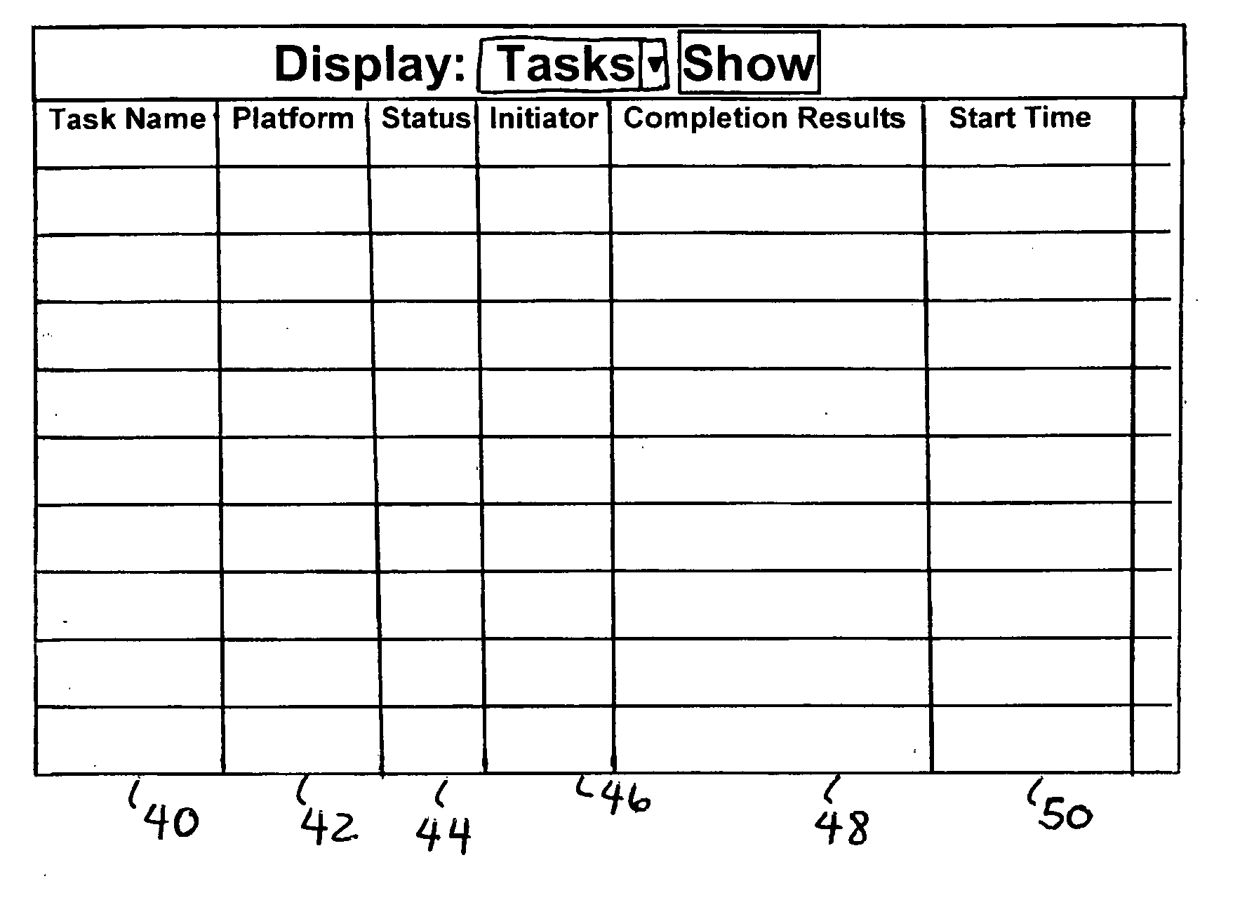
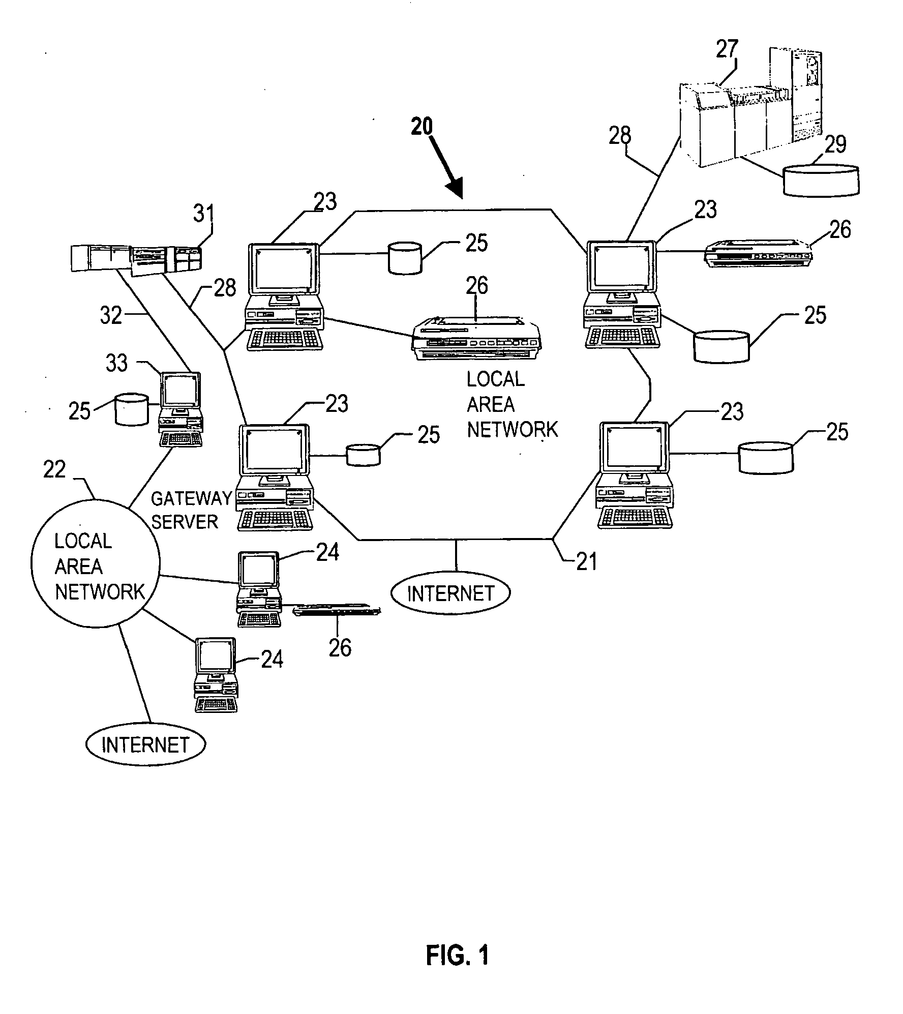
[0023] The implementation of the present invention can be within a computing system environment such as a distributed computing network. With reference now FIG. 1, there is depicted a pictorial representation of a distributed computer network environment 20 in which one may implement the display method and system of the present invention. As may be seen, distributed data processing system 20 may include a plurality of networks, such as Local Area Networks (LAN) 21 and 22, each of which preferably includes a plurality of individual computers 23 and 24, respectively. Any of the processing systems may also be connected to the Internet as shown. As is common in such data processing systems, each individual computer may be coupled to a storage device 25 and / or a printer / output device 26. One or more such storage devices 25 may be utilized, in accordance with the method of the present invention, to store the various data objects or documents which may be periodically accessed and processe...


PUM


Abstract

In a computing environment, a display shows the progress of the execution of a user or system initiated task. The display includes the current completion status of the task, and the completion results of the task. The completion results indicate the amount of the task that has been completed and indicates the results of the completion. This displays differs from conventional task status displays in that this display gives information about the progress of the task execution and the activities that occurred during the task execution.

Description

FIELD OF THE INVENTION [0001] The present invention relates to a display that indicates the status of a tasks executing in a computing system environment and in particular to a display that indicates a current status of a task executing in computing system environment including an indication of the percentage of the completed and results of the completion at various phases of the execution. BACKGROUND OF THE INVENTION [0002] Many tasks are executed on a computing takes various amounts of time to complete. Most computers have a display indicator to inform the user of the percentage of the task that has been completed and the amount of the task that remains. With the advent of the graphical user interface (GUI) on computer systems came the increasingly common practice of informing a user of the progress of any past or functions invoked by the user within the application. This practice has become popular because it is interactive with the user and keeps the user apprised of how the fun...

Claims


Application Information

Patent Timeline
IPC IPC(8): G06F3/01
CPCG06F3/0481
Inventor BELL, DENISE ANNKISSA, PETERMATHIEU, ARNAUD AIRY
Owner IBM CORP
Why Eureka
Eureka Blog
Learn More